Howdy, Stranger!
It looks like you're new here. If you want to get involved, click one of these buttons!
Quick Links
What is the meaning of the appearance of horizontal lines in the layout layer?

In the layout generated by KLayout, one can clearly observe the appearance of many horizontal lines. These horizontal lines have no spacing between them and are usually rather short, so the waveguide is essentially connected. However, in this particular case in the figure, there is one very long horizontal line that runs across the waveguide. This line originates from KLayout itself and cannot be merged (after applying merge, the line disappears, but once saved and reopened, the line reappears).
After fabrication, we found that this section of the waveguide exhibits unexpected reflection. Our current analysis suggests that this horizontal line may have a physical meaning in the stepper lithography process—namely, that when reaching a boundary, the stepper turns off the light source.
Therefore, I would like to know how such zero-distance horizontal lines are generated in KLayout, what their actual significance is, and how they can be eliminated? Thank you.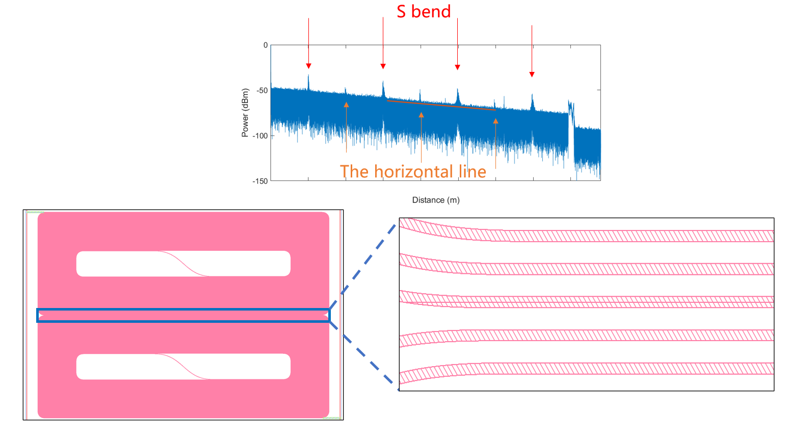
Comments
Hello,
This is not KLayout related but GDS/OAS format related...
https://www.klayout.de/doc-qt5/programming/geometry_api.html#h2-171
==> Polygon objects are not compatible with the GDS2 or OASIS format and will be converted to SimplePolygon objects by introducing cutlines when writing them...
Moreover, the GDS format has a vertices limit, with older versions of the format limiting polygons to 200 vertices, while modern GDSII specifications support up to 8191 vertices per polygon, so polygons with more points will be fragmented resulting in these horizontal lines when writing the GDS file.
Cheers,
Tomas
Hello,
First, I assume you saved the design in GDS2.
These (horizontal) cut lines are inevitable if...
1. A shape is represented by a polygon with holes OR
2. A polygon contains too many vertices (number is somewhat controllable; see below).
Does your case meet both conditions?
1. Initial design with PCells
2. Flattened PCells
3. Merged polygons
4. An idea to eliminate the horizontal cut lines
5. Other ideas
I'm totally unfamiliar with the type of lithography equipment you're using, but...
1. Divide the design into two regions in the X direction and three in the Y direction. The dividing lines in the Y direction should run through the wide spaces.
2. Allow a slight overlap at the dividing boundaries.
3. Increase the resolution of your lithography equipment.
etc.
Kazzz-S
Many thanks to the experts above for their professional and timely answers. I also tried the suggested methods and found that by merging only the two sections where the long horizontal lines appeared, the horizontal curve disappeared smoothly! I would like to summarize the issue here, hoping it may help others with similar problems:
The reason for the horizontal lines is that the number of vertices in the polygon exceeds the limitation of the GDSII file format. For DUV steppers, such boundaries mean the light source switches off. If such a horizontal line appears in the middle of a waveguide, it can cause uneven exposure.
The solution is to split the original polygon so that the cut lines are as short as possible.
Once again, many thanks — this has deepened my understanding of the GDS file format.
Great discussion") Thanks!
Thanks!
@Chen_0925: I don't know the system you're working with, but I think it has a flaw when it creates lithography artefacts in such cases. Cut lines are very common in GDS as they cannot be avoided. You can do decomposition into convex parts to eliminate the holes, but that will introduce even more cut lines.
As you say steppers I guess you mean reticles. Reticles are typically manufactured on e-Beam or laser writers. These produce an image that is obtained by digitizing a GDS file. For this step you need software that converts GDS into the mask writer's internal format. That software should be able to eliminate the cut lines. IMHO, this is one of the minimum requirements for such a tool.
Matthias
For the R&D-grade e-beam writers (even such as modern Raith tools or Crestec) there are still different issues concerning the handling source GDS geometry via pattern generator rasterization algorithms. One of them is that it cannot judge whether the cut line is unintended or not, so it could make a virtual border of an element, splitting the pixel streams on different sides of the cut line. So in some cases it is vital to have the cuts in specific places only and/or in specific direction to obtain optimal pixel stream distribution when rasterizing. Different pixel streams could give possible misposition ca 1-20 nm (or even worse) depending on a hardware type, substrate type (dynamic charging effects), writing times (system drifts between applying the pixel streams). So the defects of element's edge could easily arise.
I often have to make trickies to get rid of undesirable cut lines, mostly using Separate command by splitting the element into pieces and merging them in a different way.
In general splitting the elements itself is not a problem for technology. You only have to do it wisely.
I wish I have an option in KLayout to choose the cut lines locations, e.g. to not to have sharp angles because of cuts (e.g. for a ring you can cut in a normal direction somewhere but not just horizontal cut somewhere at an edge of ring, thus making the sharp angle)
@Chen_0925 Concerning the cut lines: it is not about vertices amount for any specific poly, it is a way to represent filled regions with holes with only one polygon record (a single sequence, a list of vertices). It is related to GDS-file format, which generally describes only filled polygons (which has physical sense since it is about IC elements) in contrary to the AutoCAD DXF approach, where you have Hatch entities separated of Polygons itself, because it was firstly developed for design blueprints and not for direct machining.
I am not familiar with tool specific GDS software except Raith and a Beamer, but there are still no reliable way to work with multiply-connected regions (with holes) in fully automatic regime while you rely on GDS-file sources. Anyway you need to deal with tool&process-specific features, especially when working in tens of nm domain.
I don't know about modern mask fab algorithms or nuthin', but my gut says those would be better able to deal with more, smaller, less complex polygons / shapes than the kinds that require klayout, and maybe mask fracture differently, to think up its own "retrace lines". I do like to merge me some ortho power busses but the way I lay out and the designs I do, that's still sub-100 vertices and all 45 / Manhattan.
Anyway simple is good if shape count is not your bind, right?
Of course an incoming GDSII, is a done deal, you got what you got.
@dick_freebird As far as I know for e-beam tool specific features, such as raster kind of exposure, beam sweep velocity limitations, and other different physics related issues, it is rather tricky to adopt arbitrary shapes into beam XY-deflection sequences combined with blankings (beam off states). Every manufacturer makes its' own approach to that problem, usually starting with some kinds of Manhattan cut. There could be some special algorithms for specific types of shapes, e.g. circles or elliptical shapes (rings too), or grating type shapes (photonic crystals too) etc.
Looks like generally you're right, but fortunately not as deep
In my practice the more prework you do - the less "issues" you will have with your patterning tool, when you don't have much "power" over proprietary behaviour...
Hi @mad_drummer,
then your manufacturer does a bad job.
GDS2 is an artwork format. If they simply take that and feed it into the e-Beam writer, then that is naive.
For VLSI masks (reticles) for example, GDS2 is not used as a data exchange format. A de-facto standard is MEBES, which is a flat representation of the geometry in form of non-overlapping trapezoids. This format used to be the native writer format for ETEC e-Beam mask writers several decades ago, but is still in use. Software exists that converts artwork GDS2 into MEBES. With KLayout you can achieve something similar by merging your polygons and performing a trapezoid decomposition on them. This can be done in DRC for example.
KLayout also has a polygon-with-holes representation, but that can't be written to GDS2. GDS2 does not support polygons with holes. The way the polygons are made is part of the stitching algorithm and I am not willing to spend effort in improving it, to solve a problem that others should take care of.
BTW: Some time ago, I tried to establish a contact with Raith regarding their very special flavor of GDS, without success. So either they have their own solution they want to sell, or they are not interested.
Matthias
Hi @Matthias,") And yes, everytime I have to make less or more prework on every pattern to have it patterned in a proper way. Unfortunately, mostly it is not more to different feature size (and dose) corrections as it is commonly thought for e-beam litho, but to make optimal splitting of the polygons to prevent undesired side effects of the software-hardware.
And yes, everytime I have to make less or more prework on every pattern to have it patterned in a proper way. Unfortunately, mostly it is not more to different feature size (and dose) corrections as it is commonly thought for e-beam litho, but to make optimal splitting of the polygons to prevent undesired side effects of the software-hardware.") ) Some of them even got stuck to DXF made of unconnected(!) lines within 1 nm grid, which I manually redraw according to my needs. In that case I honestly prefer to have hand drawn paper sheet with dimensions.
) Some of them even got stuck to DXF made of unconnected(!) lines within 1 nm grid, which I manually redraw according to my needs. In that case I honestly prefer to have hand drawn paper sheet with dimensions.
In this case I am the "manufacturer" working on Raith tools
When dealing with my "customers" I always try to teach them the best way of giving me the patterning data, but in our case of mostly scientific institutions it is rather hard to teach somebody
Concerning the Raith: had they replied to you at all? And on their software - they have their editor in the NanoSuite SW still based on GDS-type of data. Also they have a (collab?) BEAMER option for their tools to make some tool-specific optimizations. And you definitely realize the prices for all of that... AFAIC their SW team is a kind of top in the hierarchy of the company, so it is rather hard to deal with them even for their main team") (or at least it was so back in the previous days).
(or at least it was so back in the previous days).
P.S. Thank you for your huge effort in creating and maintaining the KLayout tool!
Hi @mad_drummer,
So far, Raith has not come back to me, but after all, I'm a private person with a spare-time project, so maybe they don't consider me a suitable partner to talk to.
What you describe definitely calls for a better solution. Beside trapezoid decomposition, KLayout offers Delaunay triangulation with adjustable resolution and angle constraints and Hertel-Mehlhorn convex decomposition based on the Delaunay triangulation. While the latter is kind of experimental, Delaunay triangulation can give you a deterministic decomposition into triangles with guaranteed minimum corner angles:
I'm not sure if that helps. At least that provides a kind of normalization without cut lines.
Matthias