Howdy, Stranger!
It looks like you're new here. If you want to get involved, click one of these buttons!
Quick Links
layout2fc: a python script to export a 3D structure from klayout (work in progress)

Here annexed the script. Usage: layout2fc.py -stack stack_file dxf_file
More details on its utilization can be found at:
https://github.com/realthunder/FreeCAD/issues/422
and
https://github.com/realthunder/FreeCAD/issues/419
Comments
The script is updated and successfully tested on a simple case. Updated script and more details at:
https://github.com/realthunder/FreeCAD/issues/422 .
Hi Matthias, I would like to extend a little bit the capabilities of my script.
To do that I need to extend also the stack format adding two columns holding (for each layer) the kind of operation and the insertion order. In the previous version I was using datatype to define the insertion order but I think that it is better to have a separate data field. The new format is better explained in following lines taken from annexed file UMS_PH10.stack
The first line with scale is used to convert FreeCAD unit (mm) into micron.
The line: 49/0: 0.0 70.0 add 0 # DIEL_GaAs
means that layer 49/0 defines a vertical solid extrusion from h=0 to h=70mu, the last number (before the comment) refers to the ordering of the related CAD operation. The order is important for the ins (insert) operation which consists of a solid extrusion plus a cut of all previously created solids which intersect the new one.
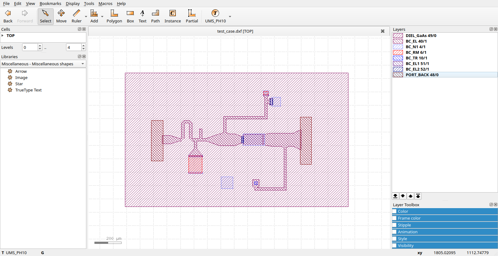
The last line should produce a vertical surface (instead of a solid object) using the sketch profile stored in layer 61/0. But here there is a problem. I wanted to make a single face extruded from a line defined by a klayout path with 0 thickness. If you have installed the RT branch of FreeCAD (https://github.com/realthunder/FreeCAD/releases/tag/2022.07.09-edge) you may check the annexed script and test case by giving the command:
The script will stop at line 139 where there is pdb.set_trace(). You may continue a few times until you find opi=='vsurf'. At that point the script will have written a file named "test_case_SPLIT_1.dxf". This file should contain a single line generated by the path but when I open it I can not find anything.
Sketches associated with other layers which contain polygons (instead of lines) are OK and FC is able to use this kind of data.
@wsteffe That is really awesome!
A humble suggestion: maybe you want to put the script on GitHub or GitLab instead of attaching .zip files here - that way you will reach a broader audience and it's an invitation to others for contributing or testing.
Thanks for this sample code for the FreeCAD library. I used FreeCAD myself a little, but honestly I did not really understand all concepts. Maybe I should approach that tool from the Python side")
Best regards,
Matthias
@Matthias, thanks for your interest.
I forgot to say but I have already put this script into the git repository https://github.com/wsteffe/layout2fc
But I think that only you may tell why the file "test_case_SPLIT_1.dxf" (written for layer 61/0 of file test_file.dxf at line 127 of the script) is void. If you open the "test_file.dxf" with klayout you will find a single line on that layer but it is not written in "test_case_SPLIT_1.dxf".
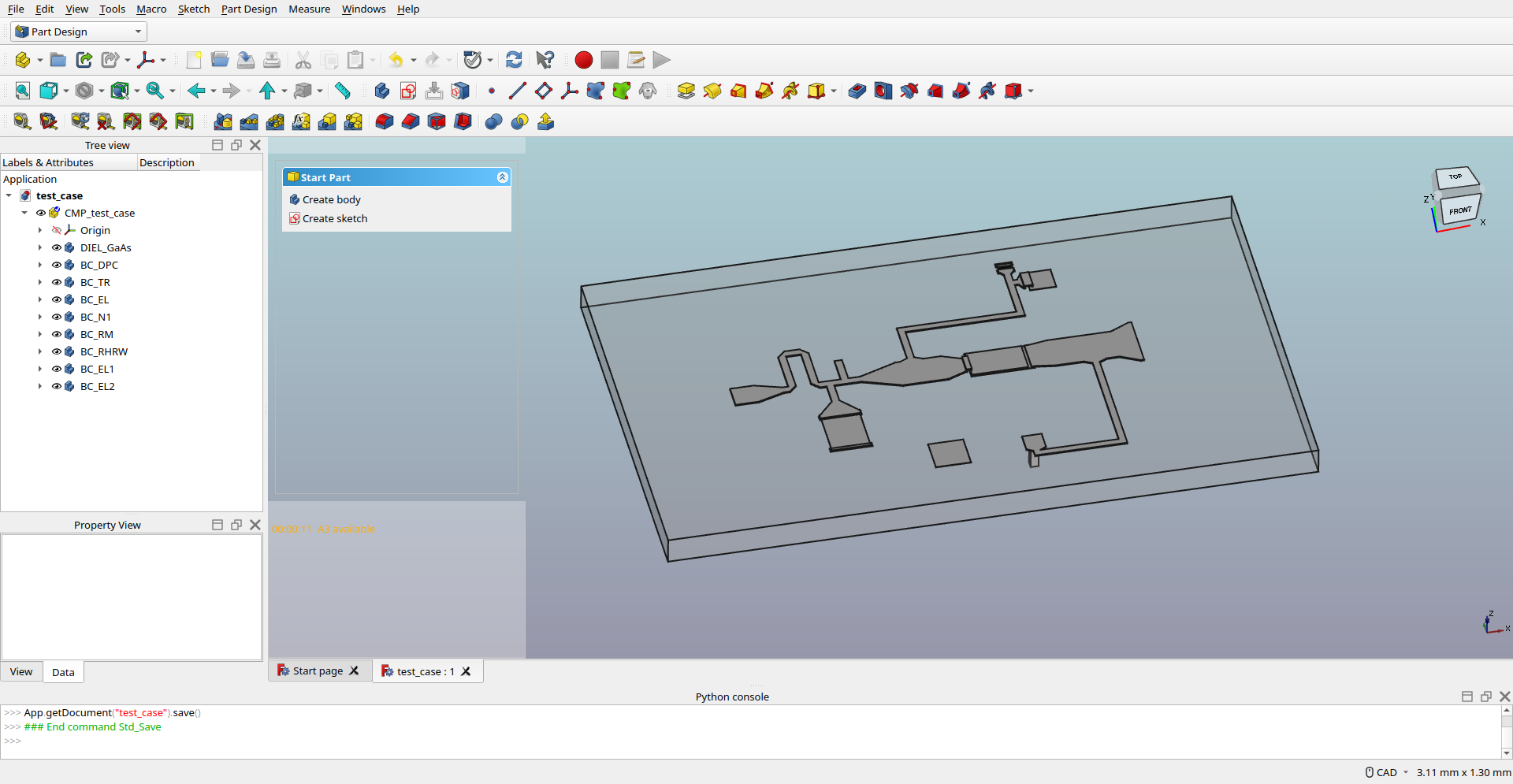
Regarding the complexity of FreeCAD I may understand the difficulties but I think it is better to start with the GUI. Unfortunately the python interface is not well documented. I was able to write this script only thanks to the help of Realthunder which has been very helpful (see https://github.com/realthunder/FreeCAD/issues/422).
There are several tutorials on the net (also on youtube) about FreeCAD usage.
You may start, in example, from https://wiki.freecadweb.org/Tutorials.
FC is composed of several WBs (Work Benches) and you may switch between them with a start menu near the upper left corner. The most important WBs are PartDesign and Part. Sketch WB is also used very much but usually I call it from the PartDesign WB. Part and PartDesign have similar names and are both aimed to the creation of solid objects. The main difference is the kind of design flow. Part is mostly based on solid primitives (Cube, Sphere, Cone...). In PartDesign typically you start with a planar sketch that is then used to create a solid object by extrusion PAD), revolution or other operations.
I have just understood why the line on layer 61/0 was not written into file "test_case_SPLIT_1.dxf" .
It was simply deleted by the merge operation which was applied to all layers.
Only closed polygons survive to this operation. So now I have excluded from merging the layers used to define vertical surfaces.
Hi Matthias, I would like to ask you if it were possible to have an option to reconstruct arcs and circles after merging operation.
Circles discretization is a very big problem for 3D CAD structures (see last posts at https://github.com/realthunder/FreeCAD/issues/422). Each via hole (and there may be many of them in a PCB or MMIC structure) is converted into a geometry bounded by many small vertical faces (instead of one).
I think that it shouldn't be very difficult to reconstruct the original arcs/circles after the merge operation. But you have to keep track of circles (an integer tag will be enough) associated with vertices produced by the discretization.
A circle tag has to be assigned also to any new vertex (produced by the fuse algorithm) if that vertex belonged to a circle segment.
At the and of the merging the polyline associated with a discretized arc may be replaced with the analytic arc defined by the two extremes and one inner vertex.
That is going to be difficult as there actually is no arc inside KLayout - only polygons. Plus there is gridding and the vertexes snap, so numerical accuracy is bad. After all, KLayout is a VLSI mask tool.
This will both make reconstruction of arcs difficult. I'm sure such an algorithm can't be built, but I don't have one in stock.
Matthias
Ok Matthias.
I think that it will not be a problem for layout2fc which can be restructured to use FC internal libraries for merge operations (instead of using klayout).
But I thinks that it is a pitty that internal representatoin of kalyout is limited to polygons.
It would be sufficient to add bulges to some segments to convert them into arcs (as done in dxf Polylines). And there are open source libraries (in example CGAL) which can do booleans on such generalized polygons composed of arcs and straight line segments.
I may understand that you do not feel the necessity of this generalization working in the VLSI domain but a Layout Editor could be useful also in other domains at several different scales (such as PCB, LTCC, MMIC, planar microwave antennas..) which could benefit of analytic circles.
@wsteffe I understand the desire in general, but really going to arc mode is a hell of a project.
Right now, everything in the layout database can be represented by polygons, hence that is the basic object. The Region class - which is the representation of "everything" - is based only on polygons and so are all algorithms inside KLayout. Extending that to other shapes means to restructure the database and all algorithms which is equivalent to rewriting the application.
For example, boolean operations that maintain arcs are a very different class of algorithm compared to the straight-line polygon one.
VLSI layout is kind of special - in most cases, the features are even rectangular. But there are literally billions of shapes. Handling this complexity can only be done at the cost of specialization. That's why you cannot load even a small chip design into AutoCAD.
Matthias