Howdy, Stranger!
It looks like you're new here. If you want to get involved, click one of these buttons!
Quick Links
VERY IMPORTANT: gds exported from K layout not working on Cadence at foundry

I had designed a chip using K layout and saved it as gds and send it to foundry. But they replied its not proper. So we also checked using GDSII viewer software and found the gds didn't showed full circuit. later I send him the dxf file and he opened it on cadence and saved it as gds. again we tried to open that newly created gds, it opened in every gds viewer very well.
All the structure, layout hierarchy and even variable names are same, and also the size of gds saved from cadence is same; But why can't my file exported from K layout not working well?
All the structure, layout hierarchy and even variable names are same, and also the size of gds saved from cadence is same; But why can't my file exported from K layout not working well?
Comments
I think I made a mistake while designing. I used to save the file in gds while I was designing. I figured out that I need to save it in dxf during the design phase and only after finishing the design, I need to save as gds. This way the file worked.
But I am still not convinced that why saving in gds and editing file gave me a problem whereas saving in dxf and saving to gds at the end has no problem at all.
It has always worked for me. Perhaps you have a setting set wrong. For example when you go File > Save As, there is a dropdown "Layers to save", which should be "All". That might be set to "Visible layers only". Or there could be other reasons.
Anyway if you can upload a test case somewhere, that is a dxf and after saving to gds you find some parts missing, then I can see if I can replicate that. Bonus points if you include the incorrectly-generated gds file that goes with that dxf so I can see exactly what is missing.
Anyways, how can I upload my design? I can upload my sample design for you. So that you can help me figure out how is it possible. while viewing at k layout all 3 looks same, but if checked from another viewer, only that was generated from dxf works.
There's no way to upload it here. You have to upload it somewhere (like dropbox) and then you post a link here
And thank you in advance. I am also too curious about that small difference.
https://drive.google.com/drive/folders/1ImMmJTmVsCYnNk1Jyucp-L1vUonn8s3x?usp=sharing
Hi,
If I understand you correctly, you need to save to DXF to get a correct GDS file? I'd not recommend this path as DXF is not really suited for mask layout - for example, DXF is lacking drawing unit information. GDS (or OASIS) are made for this purpose, so with DXF you can only go wrong.
Could you be a bit more specific what the problem was? Did your foundry tell you what issue they found? Any error message, warning or similar? Which GDS viewing tool are you using? And apparently you mask maker is able to turn a "bad" GDS file into a good one using Cadence, right? So how can Cadence do that well when another tool can't?
Looking at your test data, I found only minor differences in "test.GDS" and "test from dxf.GDS". For example, in "test.GDS" the "Grating2" instance is a single-instance AREF (an array with 1x1 instances). Such instance are not illegal from my point of view, just useless. These instances are turned into single instances on various occasions in KLayout - maybe on DXF read or write. So if you mask maker or your other viewer tool can't read those AREFs, this would provide an explanation.
But I often encounter these kind of useless AREFs in other layouts and they seem to be common. So I can't really believe they are responsible for serious issues. Every tool I know can deal with this case properly. Only very old software might be overly picky with respect to such cases. Maybe your foundry can provide you with information about the GDS features allowed. Often old tools have other limitations too, like the number of points per polygon and path, the maximum layer number, length of cell names, characters allowed in cells names and such. You need to be aware of such limitations to be avoid further issues.
The OASIS standard is much better defined this respect, so IMHO this should be the preferred exchange format. But that's a different topic.
Regards,
Matthias
My problem was:
I had designed two similar layout in a single reticle(dividing it into two). The only difference between those two layouts are the grating couplers. I wanted to examine the effect of different gratings.
But when we send the file I made (generally I used to save it in gds during design), the gds viewer showed only half portion and that was also moved here and there. It was a total mess.
So, we sent them dxf file to see how the design looks, and they opened that dxf in cadence and saved it as gds. And the result was correct.
Hearing that I also tried saving my file in dxf while editing and finally saving in gds. This time the file worked well in all gds viewer.
So I was curious what made these difference.
UPDATE: I have added a new folder with screenshots of the views in the drive. Please have a look.
You can see the layout from dxf is exactly as seen from K layout. But in another case, the texts, bends and many of the instances are lost and misplaced.
Thanks in advance!
The issue sound familar to me - we've encountered an issue with a GDS viewer reading in a gds design layouted with klayout.
Reason was that the nuber of vertex when you save a gds file was set to 8000 while the gds reader we used in the past only supported a vertex number until 300. As a result polygon were cut off. If you then export or save a gds from this GDS viewer you face a real issue in the fab.
How did you set the writer option values?
In your test case I run a quick check and export one gds with 300, the other with the default value of 8000 and finally run a DIFF - there are few differences between both gds ...
We get around by using OASIS.
Best Regards,
Andy
Hi all,
After looking at the screenshots I'm pretty sure the issue is the one I was suspecting above (single-instance AREF's). All cells I see - the missing bends, the labels, the missing wiggly connection pieces are such AREF's. I have not seen big polygons - then quarter-circle bends have only 154 points which shouldn't be an issue.
You can see the single-instance AREF's when you select an instance, double click it and in the Instance Properties look at the "Array Instance" option. If it's checked and the rows and columns count is 1, you have such a single-instance AREF. There are some cases where there are true AREFs (for example, the GC_W15 instance in the upper half, left side) has 20 rows and one column.
As I mentioned, IMHO such an instance is valid although somewhat useless. DXF turns them into single instances. I don't know what the viewer you use isn't able to deal with them - I'd rather say that's a bug.
If you want to get rid of the single-instance AREF's I'd recommend saving to OASIS instead of DXF - this will also preserve the PCell instance of the labels.
Speaking of PCell instances I need to say that if you use PCells, 3rd party GDS viewers will show a strange additional top cell called "$$$CONTEXT_INFO$$$". GDS by itself is not able to store PCell data, so KLayout needs a place where to keep that. This dummy top cell is this vault. It's hidden by KLayout, but your mask maker will see it. You can either tell him to make sure to use your actual top cell (they should be able to select only this one), or you save with the "Cell context" option OFF (under "Generic Options"). But after this of course, your PCell instances became ordinary ones. So you do this as the last step.
Kind regards,
Matthias
And as I came to know that using OASIS format is the best way to get things around, I will take that in mind and my future designs will be done in that format.
Thanks once again to this wonderful forum for letting me learn new things pretty quick.
With gratitude,
Bishal Bhandari
Some other tools do not allow non-orthogonal instance arrays: if I remember well, Cadence will just skip them (other tools might just convert them to orthogonal arrays messing up the design)...
To be safe the row vector(x,y) x-value should always be 0, and the column vector(x,y) y-value should always be 0...
There is a Warning in the "Object Editor Options" window for this...
Maybe an option can be added not to allow non-orthogonal instance arrays at all, for instance in the Setup menu...
Cheers,
Tomas
Hi Tomas,
thanks for the clarification. Frankly I'm not aware Cadence is still having this issue. I though that has gone long ago. I see a lot of GDS myself and non-orthogonal arrays are pretty common. And OASIS is very specific here: any kind of array is allowed. An OASIS compliant system has to be able to digest non-orthogonal arrays.
But I still think the original issue was not related to orthogonal/non-orthogonal arrays. Rather to 1x1 arrays which are not real ones.
Thanks,
Matthias
I did some small tests, and the Cadence version I tried does not allow non-orthogonal arrays, they are just skipped...
Warning message: ...having non-orthogonal vectors made from three points specified as (25600,0) (40600,0) (40600,15000). This AREF geometry cannot be computed correctly and therefore, will be skipped. This problem can occur if the software used to produce this file malfunctioned or if the file is corrupt... :-O
And I can't find any import options to allow them...
A 1X1 array is imported correctly, but as a single instance, not as a 1X1 "mosaic"...
I use 1X1 arrays sometimes, as it makes it easy to make dense structures (yXy array) from an isolated structure (1X1 array) by just changing the array properties and did not have any issues with that so far...
Cheers,
Tomas
Hi Tomas,
I disagree with the term "malfunctioned" ... it's a know issue that Cadence can't digest AREFS which don't fit to their mosaic concept. But at least a warning given and more recent version should be able to import AREFs of any kind.
But the testcases you sent don't contain such AREF's. Apart from the 1x1 ones (which I see to have disappeared in your screenshots), there are only 20x1 ones with a step vector in y direction and (0,0) in the 1 dimension. So nothing non-standard here.
What's wrong with this test case then?
Matthias
I also don't agree with the message Cadence created... ;-)
I've got only access to version IC6.1.6...
I didn't sent/refer to any test case, I just quickly drew an orthogonal, a non-orthogonal 5x5 array and a 1x1 array in KLayout and streamed them in into Cadence to see what happens (ok, skipped, ok)...
Maybe we can conclude that one needs to be careful when using gds files on older tools...
Cheers,
Tomas
Hi Tomas,
true ... that's why I added the warning to the "Instance Properties" ("Some design systems only accept orthogonal arrays") :-)
IC6.1.6 is actually not that old. I thought they had fixed that. I wonder what they do with OASIS ... I can consult some Cadence experts. Maybe they know more about those details.
Regards,
Matthias
Hello Matthias,
We now quite often run into the issue that $$$CONTEXT_INFO$$$ creates problems with a simulator we import the GDS into. The problem here are the $$$ let the simulator fail.
A solution to switch complete to OASIS is yet not always an option.
Is teure a way to disable the cell context by default? It is enabled every time new you start KL.
Probably an option in the general writer setup?
Another way may work is to run a small py code loaded at the start pre-setting the write_context_info=False in writers option (need to test it).
Thanks and Best regards,
Andy
The Tanner-based foundry I am working with also has problems with the $ character inserted when multiple instances of different attributes but same master, or same name but different master-source (like importing "contact10x10" twice because it sits at the bottom of every device I imported from their test chip DBs to my design DB) are found. They made me chase out all of the offending cells - even though they existed in the incoming databases as well. I think it was really Caliber (or the Tanner "lite" version) that was puking, not the L-Edit itself.
Is there perhaps the option to pick and set the "I already got one" character to one that isn't widely considered to be a comment character? Like could we have a field-chooser that offers "$" (for normal, even if problematic), "%" (nobody uses % for much that I've seen), maybe some of the other not-commonly-having-alternate-meaning ASCII characters?
Or, maybe someone could make a utility that scrubs GDS-II files for "$" and changes it (I hesitate to suggest simply turning sed or vi loose on a GDS-II file, the 8th bit and all) to a benign character of your choice?
I'd be somewhat curious whether you saw the same problems if you import your exported "problem DB" to a clean project. That is, separate the N limit from the "$" problem (presuming it's not both).
Hi Andy,
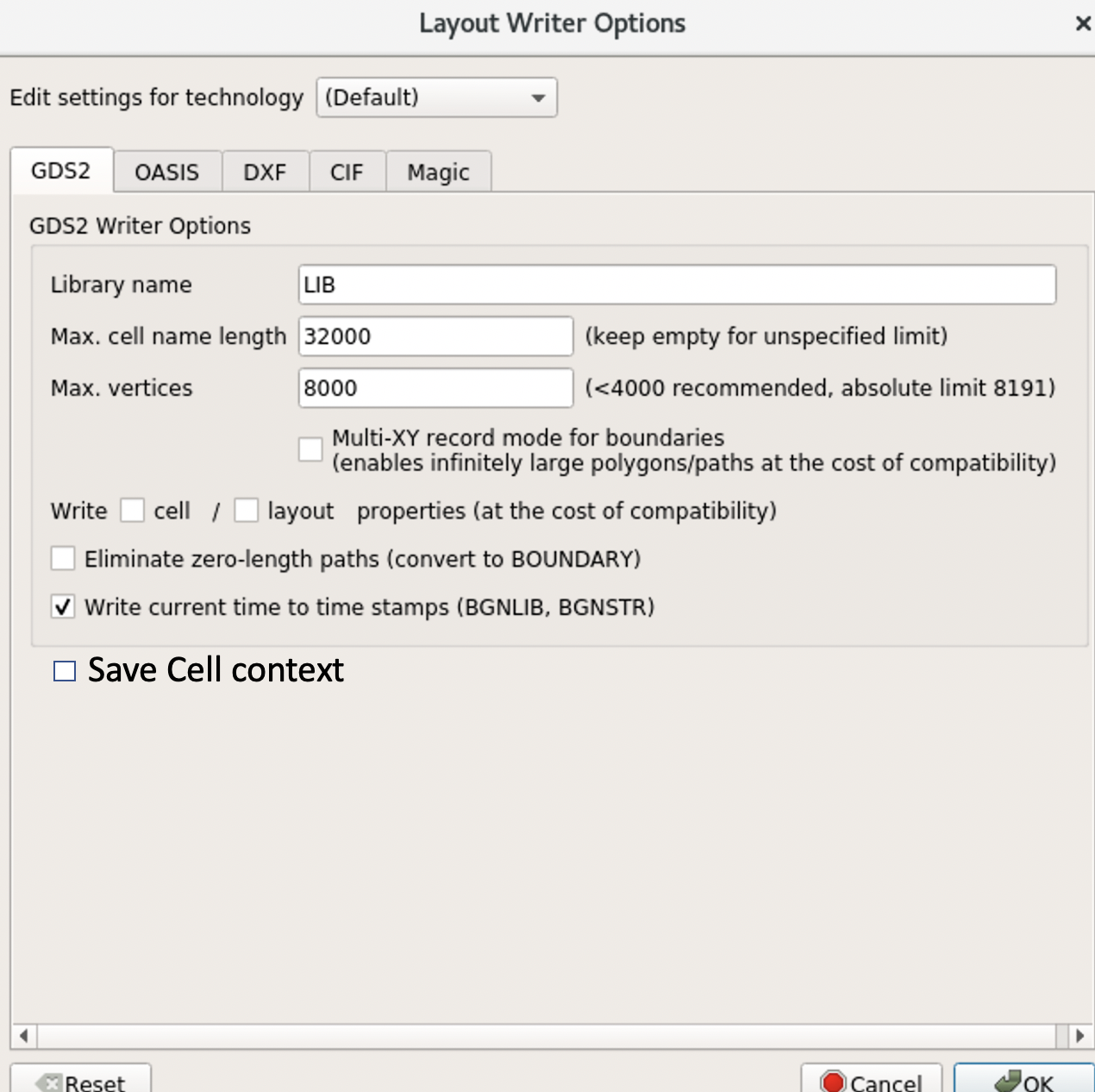
you can clean your layout by dropping the PCell context information: choose "Save As" and in the save options dialog uncheck the "Store PCell and library context information" check box, like here:
Matthias
And regarding the "$" character: I see many GDS files streamed out from Cadence containing "$" characters. So unless the foundry doesn't want to be compatible with Virtuoso, "$" seems to be a valid character.
Matthias
Hello Matthias,
Thanks for your feedback.
I know the option - it works perfect. Unfortunatly it's every time new enabled you restart KL.
I was looking to disable it in settings but can 't found an option. Would it makes sense to add it to the writer options:
Regarding the $ - your right, virtuoso stream it out too (and others). If it's inside the string it is a valid pattern - probably other tools can't handle a $ at the beginning. Cadence has no issues with the gds file.
The Simulator I'm referring too is a 3D MOS extractor from Silicon Frontline to get the rdson value.
Best regards,
Andy
Hi Andy,
I consider it too risky to put the "dangerous" features into the persisted writer options. If you don't save all layers or you skip the PCell context information you might save your layout and loose parts or all of your work. Hence I think it's safer not to make these options persistent and to require users to make this decision explicitly.
But of course you can create a script to save the file the way you need it.
Matthias
Thanks Matthias,
Hot your point - Best way would be to make the people aware of and if to switch more over to Oasis usage.
Have a nice weekend,
Andy