Exception when calling 'LayoutView.get_pixels_with_options_mono'

Hello all,
I am trying to take an image of a layout after replacing some of the cells.
When I do this on leaf_chip.gds.gz, my python script (attached as bug_repro.py.txt) runs into the exception

ERROR: /home/james/.klayout/python/bug_repro.py:16: RuntimeError: Internal error: ../../../src/layui/layui/layCellTreeModel.cc:446 ! mp_layout->under_construction () && ! (mp_layout->manager () && mp_layout->manager ()->transacting ()) was not true in LayoutViewBase.get_pixels_with_options_mono

I try to explicitly wait until the LayoutView is no longer transacting, but that doesn't seem to help.

I've seen this error on KLayout versions 0.28.11, 0.29.4, and 0.29.5, and on both Windows and Linux machines.

Am I doing something wrong? Is there a function I should call to ensure that the view finishes construction before I take the picture?

Thank you in advance for your help.

Comments

  • Hi jamesryan,

    1. Intro.

    I'm studying this case out of curiosity.
    I could reproduce your problem with KLayout 0.25.9 on Linux Mint 20.3 and macOS Monterey.
    If my understanding is correct, you want to:

    1. Remove all references to a particular cell ("sky130_fd_sc_hd__dfrtp_1", for example).
    2. Replace those 139 references with the cell's bounding boxes (a representing box shape is in L/D=2208/0).
    3. Make the cell "sky130_fd_sc_hd__dfrtp_1" orphan.
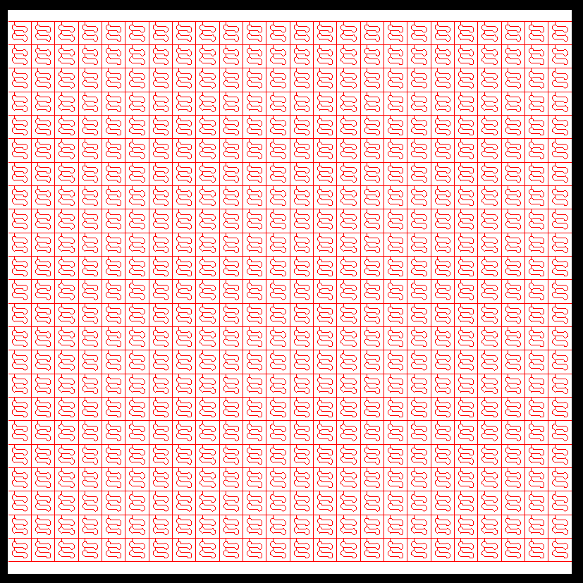
    4. Generate a monochrome image that graphically shows where those cell instances are located, as shown below.

    To be continued (assuming the above is OK).

  • Cont.

    2. Using the original bug_repro.py script

    > import os
    > os.chdir("/Users/sekigawa/GitWork/ForumKLayout/Forum/Forum2568/")
    > os.getcwd()
    '/Users/sekigawa/GitWork/ForumKLayout/Forum/Forum2568'
    Running macro /Users/sekigawa/.klayout/pymacros/Forum2568_bug_repro.py
    
    ===> RuntimeError: [reproduced!]
    ===> Generated: only ["out.gds"]
    

  • Cont.

    3. Using Forum2568_KazzzS.py

    While running the original script in the IDE, I found some points and modified the script accordingly.
    Please note that I have not fully digested your intentions.
    However, at least I could avoid the Runtime Error.

    > import os
    > os.chdir("/Users/sekigawa/GitWork/ForumKLayout/Forum/Forum2568/")
    > os.getcwd()
    '/Users/sekigawa/GitWork/ForumKLayout/Forum/Forum2568'
    Running macro /Users/sekigawa/.klayout/pymacros/Forum2568_KazzzS.py
    Index of sky130_fd_sc_hd__dfrtp_1bbox: 210
    Current number of top cells: 2
    'Number of sorted_insts': 139
    ===> RuntimeError: <nil>
    ===> Generated: ["out_KS.gds", "out_KS.gds.gz", "out_KS.png"]
                    However, <out_KS.png> seems incorrect.
    
  • Cont.

    4. Using gds2png.py

    I have modified the oas2png-new.py tool attached to Forum-2563 and wrote this tool.
    If the -l <LYP file> option is not used, LayoutView.get_pixels_with_options_mono() is used internally, and the output image will be in Black & White.

    % ./gds2png.py  -i out.gds  -t leaf_chip  -x 512  -y 512  -p _black
    ### <0001> Generating <out_black.png> from GDS2 <out.gds> ...
    >>> Elapsed Time = 3.882 [sec] >>>
    
    % ./gds2png.py  -i out_KS.gds  -i out_KS.gds.gz  -t leaf_chip  -x 512  -y 512  -p _black
    ### <0001> Generating <out_KS_black.png> from GDS2 <out_KS.gds> ...
    ### <0002> Generating <out_KS.gds.gz_black.png> from GDS2 <out_KS.gds.gz> ...
    >>> Elapsed Time = 8.758 [sec] >>>
    

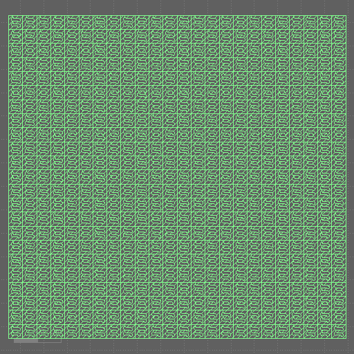
    Seeing the three image files, LayoutView.get_pixels_with_options_mono() seems to work fine.
    In other words, the root cause is likely created before calling the function.


    In contrast, with -l red_white-leaf_chip.lyp, the output image will be in Red & White.
    Again, the three image files below look OK.

    % ./gds2png.py  -i out.gds  -t leaf_chip  -x 512  -y 512  -p _red  -l red_white-leaf_chip.lyp
    ### <0001> Generating <out_red.png> from GDS2 <out.gds> ...
    >>> Elapsed Time = 4.083 [sec] >>>
    
    % ./gds2png.py  -i out_KS.gds  -i out_KS.gds.gz  -t leaf_chip  -x 512  -y 512  -p _red  -l red_white-leaf_chip.lyp
    ### <0001> Generating <out_KS_red.png> from GDS2 <out_KS.gds> ...
    ### <0002> Generating <out_KS.gds.gz_red.png> from GDS2 <out_KS.gds.gz> ...
    >>> Elapsed Time = 8.215 [sec] >>>
    

    Let me take a break here :smile:

    Kazzz-S

  • Hi @sekigawa,

    you deserve a break! Thanks a lot for your support! :)

    To @jamesryan:

    I could make the error go away by inserting this line:

    ...
    insts=filter(lambda i: target_cell.name in i.cell.name, top_cell.each_inst())
    sorted_insts=sorted(insts,key=lambda i: i.bbox().p1)
    
    # Insert this line to make the error go away:
    insts=None
    
    ex_insts=sorted_insts
    ...
    

    I am not sure what "filter" does exactly. It appears to return a "filter object" which seems to be some kind of iterator. I assume, internally it holds a reference to the instance iterator delivered by "each_inst" and this will lock the layout object - the effect is the error you observe. By setting "insts" to "None", this reference is released and the layout lock goes away.

    Matthias

  • edited August 9

    Cont.

    5. Just an Idea

    Looking at these images reminded me of Fish-finding Radar. :smile:
    How about the idea of splitting the task into two stages:

    [stage_1]. changing the cell hierarchy (like leaf_chip.gds.gz ---> out_KS.gds.gz)
    [stage_2]. image generation (like out_KS.gds.gz ---> out_KS.gds.gz_red.png)

    More precisely,

    In [stage_1], a command line tool is invoked in -H mode and accepts multiple cells to be found.

    $ ./fishfinder.py -H -i source.gds.gz -c "cell-A,1001,0" -c "cell-B,1002,0" -c "cell-C,1003,0" -o result.gds.gz


    Then, we manually edit a KLayout layer property file (myfishes.lyp) such as:

      L/D=xxxx/y White
      :
      L/D=1001/0 Red
      L/D=1002/0 Blue
      L/D=1003/0 DarkGreen
    

    In [stage_2], the tool is invoked in -G mode.
    Other command line parameters are basically the same as those of gds2png.py.

    $ ./fishfinder.py -G -i result.gds.gz -l myfishes.lyp -t pacific -x 512 -y 512
    

    Kazzz-S

  • Very cute :)

  • edited August 11

    Cont.

    6. Sample Implementation

    I tried implementing the idea. :smile:

    -----------------------------------------------------------------------------------------------------
    fishfinder.py
      << To extract the locations of specific cell instances with the help of KLayout Python Module >>
         See https://www.klayout.de/forum/discussion/comment/11182/#Comment_11182 for the idea!
    
    $ [python3] fishfinder.py
       option & argument : comment on option if any                   default value
       --------------------------------------------------------------+---------------------
       Cell Hierarchy Change Mode                                    |
        <-H|--hierarchy>: run in the Cell Hierarchy Change Mode      | disabled
        <-i|--input <GDS2|OASIS file>>: input file name              | ''
        <-c|--cell <name,L,D>>: cell to extract and its L:D mapping  | ''
        [-o|--output <GDS2|OASIS file>] output file name             | ''
                                                                     |
       Image Generation Mode                                         |
        <-G|--genImage>: run in the Image Generation Mode            | disabled
        <-I|--Input <GDS2|OASIS file>>: input file name              | ''
        <-l|--lyp   <layer property file>>: layer property file      | ''
        <-t|--topcell <top cell name>>: the top cell name for output | ''
        [-p|--postfix <pfstr>] ex. ${_output_}${pfstr}.png           | ''
        [-C|--conf  <KLayout's config file>]                         | klayoutrc
                (Linux & Mac: $HOME/.klayout/klayoutrc)              |
                (Windows: %USERPROFILE%\klayout\klayoutrc            |
        [-x|--sizex <image pixel size in X>]                         | 512
        [-y|--sizey <image pixel size in Y>]                         | 512
        [-b|--noborder] : without the image border                   | disabled
        [-d|--debug  <level>]                                        | 0
        [-?|--?] : print this usage and exit                         | disabled
       --------------------------------------------------------------+---------------------
        You may use the -c option multiple times.
            ex. -c "cell-A,1001,0" -c "cell-B,1002,0" -c "cell-C,1003,0"
    -----------------------------------------------------------------------------------------------------
    

    -H mode

    ./fishfinder.py -H \
      -i leaf_chip.gds.gz   \
      -c "sky130_fd_sc_hd__dfrtp_1,1001,0" \
      -c "sky130_fd_sc_hd__dfstp_1,1002,0" \
      -c "sky130_fd_sc_hd__mux4_1,1003,0" \
      -o out_H2.gds.gz
    
    Number of parent instances referring to <sky130_fd_sc_hd__dfrtp_1>: 139
    Number of parent instances referring to <sky130_fd_sc_hd__dfstp_1>: 54
    Number of parent instances referring to <sky130_fd_sc_hd__mux4_1>: 243
    >>> Elapsed Time = 8.261 [sec] >>>
    

    -G mode

    ./fishfinder.py -G \
      -I out_H2.gds.gz \
      -l RBG_white-leaf_chip.lyp \
      -t leaf_chip
    
    ### Generating <out_H2.gds.gz.png> from <out_H2.gds.gz> ...
    >>> Elapsed Time = 5.890 [sec] >>>


    I have modified the original code to handle a design with a multi-level cell hierarchy, as shown below.

    Cell Hierarchy Result

    Kazzz-S

  • Hi @sekigawa,

    This is amazing, as usual :) ... I hope this is what @jamesryan is looking for!

    Thanks for sharing this!

    Matthias

  • Hello sekigawa, I have been looking for a way to convert GDS to PNG recently, and I stumbled upon this post by chance. Your code has been a great help to me, and I am very grateful! However, I am now facing a new issue: how to obtain the physical dimensions from a GDS file? I look forward to your further reply!

  • edited August 13

    Hi @shawn0778,

    It's good to hear that my post is useful. :smile:

    If you mean the X and Y in the image below as the physical dimensions of a GDS file, they're easy to find.
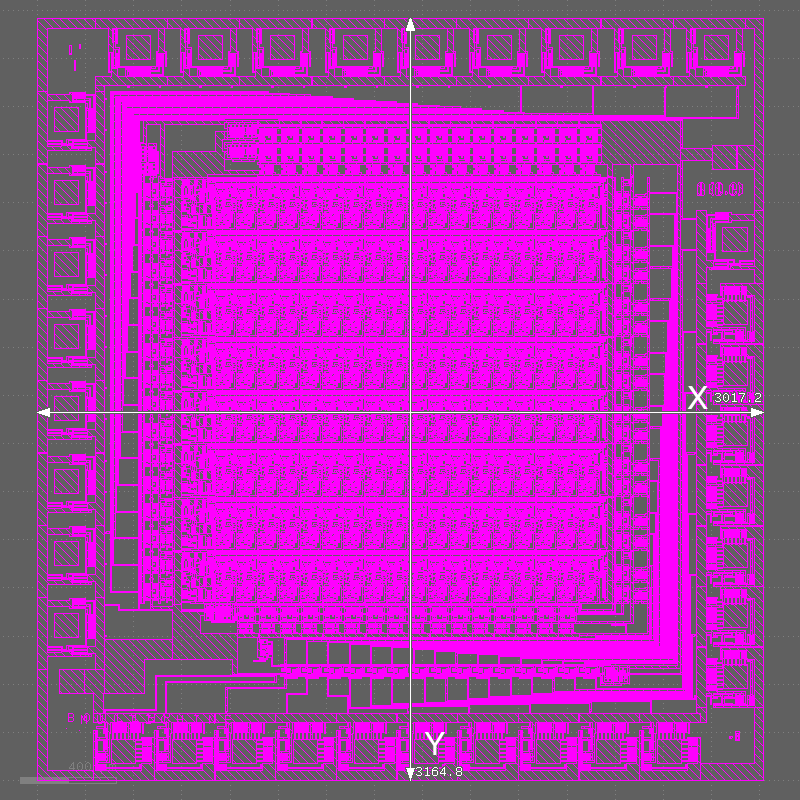
    I can modify the code of fishfinder.py as follows.

    Then I got:

    MacBookPro2{sekigawa} shawn0778 (1)% ./fishfinder.py -G -I out_Abacus.oas -l red_white-Abacus.lyp -t ABACUS
    ### Generating <out_Abacus.png> from <out_Abacus.oas> ...
    Dimensions in [um] of the top cell <ABACUS>: X=3017.200 Y=3164.800
    >>> Elapsed Time = 0.085 [sec] >>>
    

    Note that there are several sibling methods of Cell.bbox().
    See https://www.klayout.de/doc-qt5/code/class_Cell.html#method8 for more details.

    Kazzz-S

  • @sekigawa Thank you so much for your help, great (and fun) work!

    @Matthias The handle staying around and holding a lock on the Layout makes sense, thanks for your help as well!

  • I understand. Thank you again! I sincerely feel that our forum is very wonderful.

  • Hello @sekigawa ! Long time no see! The GDS to PNG conversion method you mentioned last time was really a great help. Thanks again! However, a new problem has emerged during later use. For some GDS files (such as the attached one), the image obtained after conversion using the program is empty. After multiple attempts, it is still the same. Could you please help me troubleshoot what the problem might be?

  • edited September 2

    Hello @shawn0778,

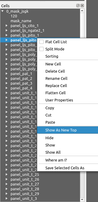
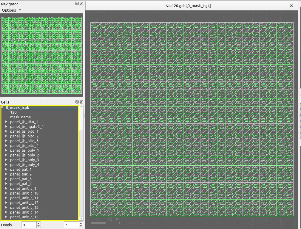
    I used the Show As New Top menu for the cells 0_mask_jsgk (top cell), 120, mask_name, and panel_xxx and found that only the top cell 0_mask_jsgk contains some meaningful shapes (23 rows x 24 columns of a polygon with two holes).

    Even if I delete all cells except the top cell, the design seems unchanged.
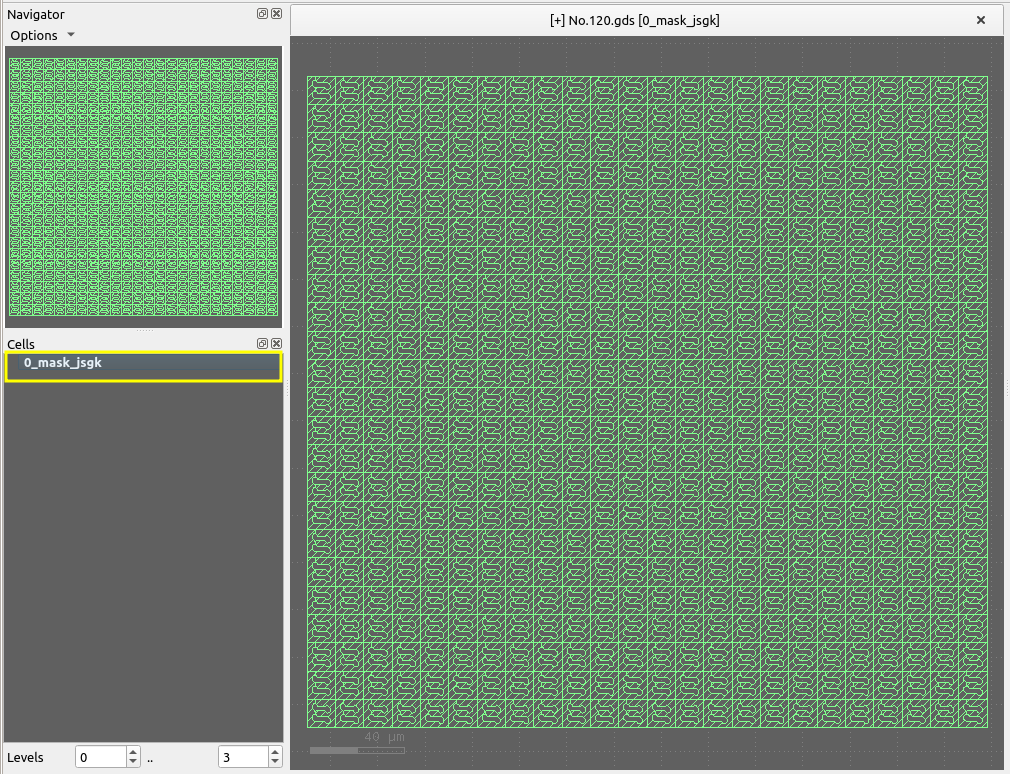
    I think there were some problems when you generated the source GDS2 file itself.


    Updated fishfinder.py: 2024-09-02

  • Thank you for your reply. I also think there is something strange about the file layers and I am contacting their provider to further confirm the issue. However, in fact, there are many such GDS files. Most of them can be converted successfully, but a small number of them will result in empty conversions. The attachment is an example file that has been converted successfully.

  • edited September 2

    In the previous example (with No.120.gds), how did you run what command?
    Please provide the detailed steps in a code block (triple single quote).

    command argument1 argument2 ...
    

    The fishfinder.py script rejects the GDS file because it has two dots in the filename (double extension) and is not considered a valid GDS file.
    If I rename the file to No120.gds and run the command below (without changing the cell hierarchy),

    ./fishfinder.py -G -I No120.gds -l No120.lyp -t 0_mask_jsgk
    

    I got


    Or did you use gds2png.py?

  • edited September 3

    Cont.

    Maybe I could find the reasons.
    1. You used gds2png.py with valid extensions (changed the file names or added more valid extensions).
    2. You did not use the [-l|--lyp <layer property file>] option as it is optional.
    3. The original color view is like this (dark foreground on dark background).
    4. In the monochrome output PNG (without using the above -l|--lyp option) , this will be black on black and, hence, disappear.

    Fix-A
    1. Change the background color to white
    2. Then, run

    ./gds2png.py -i No120.gds
    

    or

    Fix-B
    1. Keep the black(dark) background color
    2. Choose a lighter layer color and save it to a *.lyp file
    3. Then, run

    ./gds2png.py -i No120.gds -l No120.lyp


    Note that in the fishfinder.py tool (-G mode), the <-l|--lyp <layer property file>> option is mandatory.


    Updated gds2png.py: 2024-09-03 (You can add valid extensions with -v`.)

    -----------------------------------------------------------------------------------------------------
    gds2png.py
      << To convert *[.gds|.gds.gz] file(s) to PNG file(s) with the help of KLayout Python Module>>
    
    $ [python3] gds2png.py                                 (default)
        <-i|--input <GDS2 file(s)>>                        ('')
        [-v|--validext <valid extension>]                  (['.gds', '.gds.gz'])
        [-l|--lyp   <layer property file>]                 ('')
        [-t|--topcell <top cell name>]                     ('')
        [-p|--postfix <pfstr>] ex. ${_output_}${pfstr}.png ('')
        [-c|--conf  <KLayout's config file>]               (Linux & Mac: $HOME/.klayout/klayoutrc)
          The background color is taken from this file.    (Windows: %USERPROFILE%\klayout\klayoutrc)
        [-x|--sizex <image pixel size in X>]               (1000)
        [-y|--sizey <image pixel size in Y>]               (1000)
        [-b|--noborder] : without the image border         (disabled)
        [-d|--debug  <level>]                              (0)
        [-?|--?] : print this usage and exit               (disabled)
        You may use the -i option multiple times, including a wild card.
            ex. -i abc.gds  -i xzy.gds.gz -i "*.gds" (-i '*.gds' in mac zsh)
        You may also use the -v option multiple times to add more valid extensions.
            ex. -v .120.gds -v .2.gds -v .oas
    -----------------------------------------------------------------------------------------------------
    

    Update: 2024-09-03A

  • Thank you for your answer! I am very sorry that I did not describe my steps in detail, which led to some misunderstandings. First of all, I directly used gds2png.py to complete the file conversion. The specific command is python gds2png.py -i '*.gds', and I did not use[-l|--lyp <layer property file>] option.
    To avoid the problem of file extensions (because the file name is still useful in the subsequent process), I commented out this section of code so that the program can run.

    After that, I obtained the converted PNG files of all GDS files in this folder and found that some of them are empty after conversion, as mentioned to you before.

    Going back to your answer, for Fix-A, where is the first step of changing the background color to white completed and how to do? For Fix-B, referring to your previous answer, I tried to manually edit a .lyp file, but it seems that I used it incorrectly and was not able to succeed.
    RuntimeError: XML parser error: not well-formed (invalid token) in line 2, column 1 in LayoutViewBase.load_layer_props
    I am indeed a novice in this area and hope to get your more detailed guidance. Thank you for your trouble!

  • Hello @shawn0778,

    Thank you for your answer! I am very sorry that I did not describe my steps in detail, which led to some misunderstandings.
    First of all, I directly used gds2png.py to complete the file conversion.
    The specific command is python gds2png.py -i '*.gds', and I did not use[-l|--lyp ] option.
    To avoid the problem of file extensions (because the file name is still useful in the subsequent process),
    I commented out this section of code so that the program can run.

    OK, thank you for confirmation. I understood.
    The updated (2024-09-03A) gds2png.py can take additional valid file name extensions.
    In your case, you can invoke like gds2png.py -v .120.gds -v .2.gds -i '*.gds'.
    Of course, you can freely change the code.


    Going back to your answer, for Fix-A, where is the first step of changing the background color to white completed and how to do?

    1. Follow the menus: File --> Setup (Linux and Windows); klayout --> Preferences... (Mac)
    2. Choose the background color in the Setup Dialog.


    For Fix-B, referring to your previous answer, I tried to manually edit a .lyp file, but it seems that I used it incorrectly and was not able to succeed.

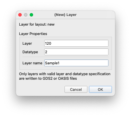
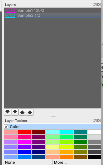
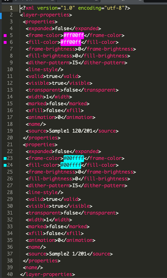
    Your sample GDS2 files No.120.gds and (120)20240722_JSGK_RA2407-UT-1_No.2.gds have L/D=120/2 and L/D=1/2, respectively.
    So, let the colors be magenta and cyan, respectively.
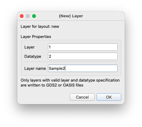
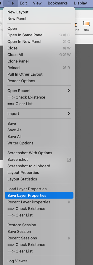
    1. File --> New Layout --> [OK] to create an empty layout.
    2. Edit --> Layer --> New Layer


    3. File --> Save Layer Properties: Save as shawn0778.lyp (see the attached file).

    Now, my work directory holds the following files.

    Then, I can invoke the tool like...

    MacBookPro2{sekigawa} xxx (1)% ./gds2png.py -v .120.gds -v .2.gds  -i '*.gds' -l shawn0778.lyp -x 800 -y 800
    
    ### <0001> Generating <(120)20240722_JSGK_RA2407-UT-1_No.2.gds.png> from GDS2 <(120)20240722_JSGK_RA2407-UT-1_No.2.gds> ...
    ### <0002> Generating <No.120.gds.png> from GDS2 <No.120.gds> ...
    >>> Elapsed Time = 0.136 [sec] >>>


  • Thank you so much! I have succeeded in using both A and B! And after some attempts, I roughly know what some parameters in the .lyp file are controlling.For example, <frame-color> controls the color of the border lines.
    However, there are still some parameters that I don't quite understand. Is there a detailed reference document available? I hope to study it further. So as to freely control the background color , line color and so on.In addition, if I want the converted image to have no reference lines and scale bars, how should I modify the parameters? In fact, when I used the python gds2png.py -i '*.gds'command before, the obtained images had no reference lines and only layers. Once again, thank you for your patient answers!

  • Is there a detailed reference document available?

    I do not know if there is such a reference document.
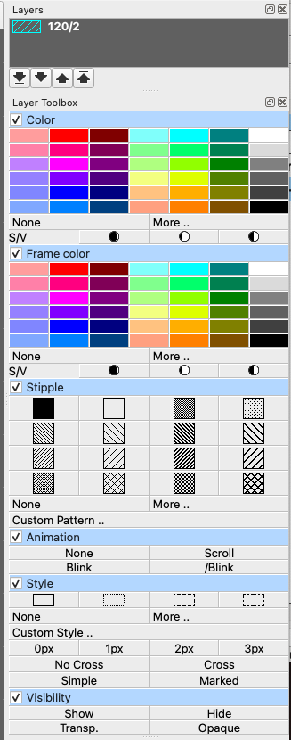
    However, the contents of a layer property file (XML) correspond to the GUI windows like

    I think the tag names are self-explanatory enough.

    So as to freely control the background color , line color and so on.In addition,
    if I want the converted image to have no reference lines and scale bars, how should I modify the parameters?
    In fact, when I used the python gds2png.py -i '*.gds'command before, the obtained images had no reference lines and only layers.

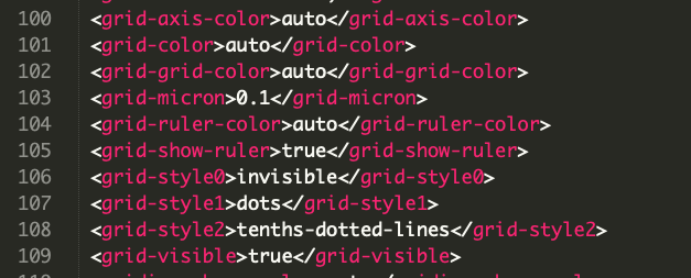
    Those user preference parameters are controlled by GUI menus here and there.
    For example, we can on/off the grid visibility by:

    And finally, they are stored in a single file: $HOME/.klayout/klayoutrc (Linux and Mac) by default, as shown below.
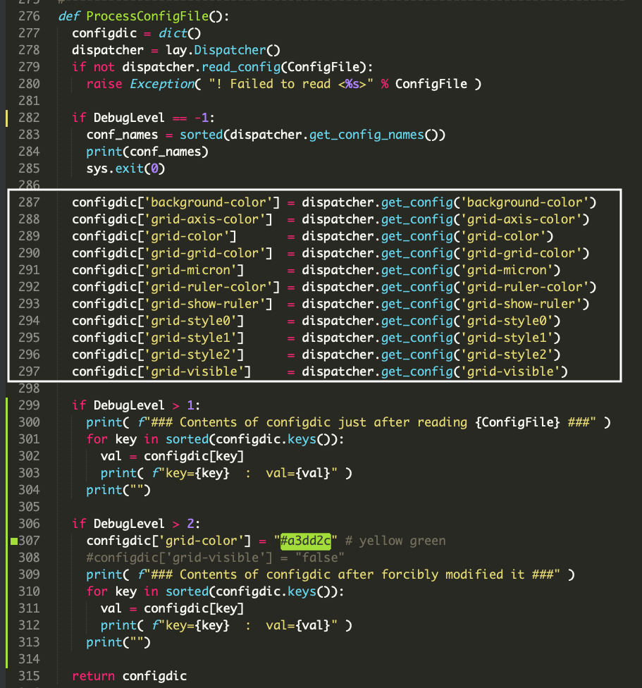
    The gds2png.py tool retrieves them back and reuses some of them (parameters in the white frame below) while generating an output PNG image.

    In other words, the output image file automatically reflects the user's last work environment.

    I have modified the script for your study. See the above code fragments.
    With DebugLevel > 2, the grid color is forcibly changed from "auto" to "#a3dd2c yellow green".

    MacBookPro2{sekigawa} cont-4 (1)% ./gds2png.py -v .120.gds -i No.120.gds -l shawn0778.lyp -x 800 -y 800 -d 3
    === GDS2 files to be processed ===
    No.120.gds
    
    ### Contents of configdic just after reading /Users/sekigawa/.klayout/klayoutrc ###
    key=background-color  :  val=#606060
    key=grid-axis-color  :  val=auto
    key=grid-color  :  val=auto
    key=grid-grid-color  :  val=auto
    key=grid-micron  :  val=0.1
    key=grid-ruler-color  :  val=auto
    key=grid-show-ruler  :  val=true
    key=grid-style0  :  val=invisible
    key=grid-style1  :  val=dots
    key=grid-style2  :  val=tenths-dotted-lines
    key=grid-visible  :  val=true
    
    ### Contents of configdic after forcibly modified it ###
    key=background-color  :  val=#606060
    key=grid-axis-color  :  val=auto
    key=grid-color  :  val=#a3dd2c
    key=grid-grid-color  :  val=auto
    key=grid-micron  :  val=0.1
    key=grid-ruler-color  :  val=auto
    key=grid-show-ruler  :  val=true
    key=grid-style0  :  val=invisible
    key=grid-style1  :  val=dots
    key=grid-style2  :  val=tenths-dotted-lines
    key=grid-visible  :  val=true
    
    ### <0001> Generating <No.120.gds.png> from GDS2 <No.120.gds> ...
    >>> Elapsed Time = 0.067 [sec] >>>
    

    Modified: 2024-09-04

  • Cont.

    If you modified the code like ...

    LinuxMint{sekigawa}(1)$ ./gds2png.py -v .120.gds -i No.120.gds -x 800 -y 800 -d 3


  • I understand. Thank you very much for your patient answers. I'm truly sorry to have troubled you!
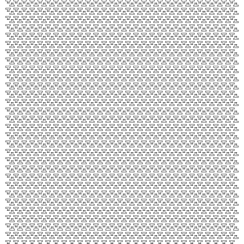
    But now there is a new problem. Here is an extremely large GDS file. By measurement, its width is 170050.0 and its height is 167525.0. Directly converting it to a PNG will lose many details. Even when opened with KLayout, it needs to be zoomed in many times to see the specific details clearly. Therefore, I have an idea. When converting, can we enlarge and convert a part within a specified coordinate range? In this way, I can traverse the entire GDS file sequentially and then obtain a complete large image with sufficient details by splicing. If we use the previously mentioned file as an example, this is the PNG obtained by direct conversion:

    This is one of PNG obtained after enlarging and converting the specified coordinate range:

    Incidentally, when I add the -b parameter, the obtained PNG is not completely without redundant edges. Sometimes there are residues on the top and bottom, and sometimes there are residues on the left and right. It's not very critical, but I'm rather curious about why this is the case. For example:
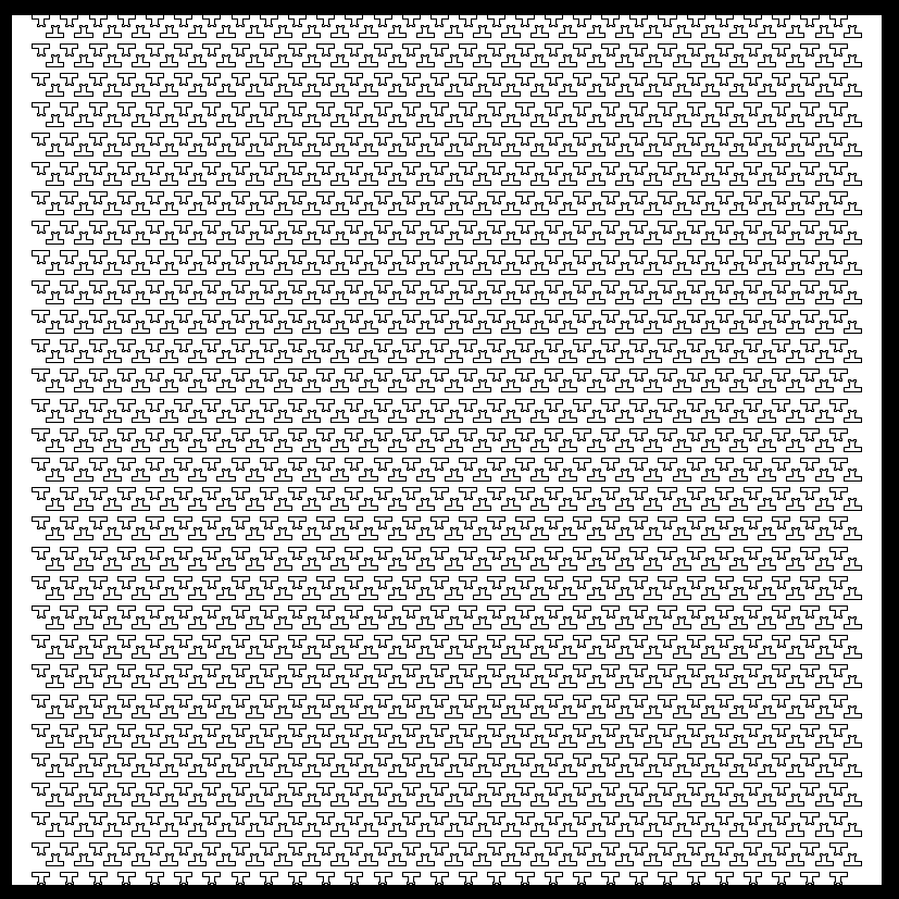
    left and right

    top and bottom

  • Let me first answer the second half.
    The top cell's bounding box is not a square in both examples.
    More precisely, in the first example, the bounding box's W < H; in the second, W > H. Whereas, the PNG image canvas is a square (1000x1000, by default). Therefore, you have some white space on the left-right or top-bottom. I think the gap will be minimized if you adjust the canvas size's aspect ratio to the bounding box's aspect ratio.

    I'll answer the first half tomorrow (hopefully). :smile:

  • Wow ...

    I came to this point while trying to follow this discussion:

    Is there a detailed reference document available?

    And yes, there is: https://www.klayout.de/lyp_format.html

    I hope it is still up to date. :)

    Matthias

  • Thanks, @Matthias; I should have searched more carefully.
  • edited September 9

    Hi @shawn0778,

    This is regarding the first half.

    When converting, can we enlarge and convert a part within a specified coordinate range?

    Yes, we can!

    I have enhanced gds2png.py:
    1. with the [-s|--split <'n,m'>] option, we can split the universe into n columns and m rows.
    OR
    2. with the [-a|--area <x1,y1,x2,y2>] option, we can specify multiple areas to extract.
    3. also added the [-g|--nogrid] option and the [-w|--whitebg] option.

    -----------------------------------------------------------------------------------------------------------
    gds2png.py
      << To convert *[.gds|.gds.gz] file(s) to PNG file(s) with the help of KLayout Python Module>>
    
    $ [python3] gds2png.py                                     (default)
        <-i|--input <GDS2 file(s)>>                            ('')
        [-v|--validext <valid extension>]                      (['.gds', '.gds.gz'])
        [-l|--lyp   <layer property file>]                     ('')
        [-t|--topcell <top cell name>]                         ('')
        [-p|--postfix <pfstr>] ex. ${_output_}${pfstr}.png     ('')
        [-c|--conf  <KLayout's config file>]                   (Linux & Mac: $HOME/.klayout/klayoutrc)
          The background color is taken from this file.        (Windows: %USERPROFILE%\klayout\klayoutrc)
        [-x|--sizex <image pixel size in X>]                   (1000)
        [-y|--sizey <image pixel size in Y>]                   (1000)
        [-b|--noborder] : without the image border             (disabled)
        [-g|--nogrid] : hide grid                              (disabled)
        [-w|--whitebg] : make the background white             (disabled)
        [-s|--split <'n,m'>] : split into n columns and m rows ('1,1')
        [-a|--area <x1,y1,x2,y2>] : DBox in [um] to extract    ('')
        [-d|--debug  <level>]                                  (0)
        [-?|--?] : print this usage and exit                   (disabled)
        You may use the -i option multiple times, including a wild card.
            ex. -i abc.gds  -i xzy.gds.gz -i "*.gds" (-i '*.gds' in mac zsh)
        You may also use the -v option multiple times to add more valid extensions.
            ex. -v .120.gds -v .2.gds -v .oas
        You may also use the -a option multiple times.
            ex. -a '4416,175736,4924,176167' -a '159680,14218,160432,14856'
    -----------------------------------------------------------------------------------------------------------
    

    Testing

    • I have created a dummy design BigChip.gds (Width=171,980.4 um; Height=180,393.6 um).

    Test [1]

    LinuxMint{sekigawa}(1)$ ./gds2png.py -i BigChip.gds -l BigChip.lyp -x 800 -y 800
    ### <0001> Generating <BigChip.png> from GDS2 <BigChip.gds> ...
    >>> Elapsed Time = 0.076 [sec] >>>
    

    Test [2]

    LinuxMint{sekigawa}(2)$ ./gds2png.py -i BigChip.gds -l BigChip.lyp -x 800 -y 800 -a '4416,175736,4924,176167' -a '159680,14218,160432,14856'
    ### <0001> Generating <BigChip*.png> from GDS2 <BigChip.gds> ...
    >>> Elapsed Time = 0.188 [sec] >>>


    Test [3]

    LinuxMint{sekigawa}(3)$ ./gds2png.py -i BigChip.gds -l BigChip.lyp -x 800 -y 800 -s '50,50'
    ### <0001> Generating <BigChip*.png> from GDS2 <BigChip.gds> ...
    >>> Elapsed Time = 189.720 [sec] >>>
    

    Note that the -s option takes a long time, depending on how many image files are generated.
    That is, order(n*m)!
    I generated an MP4 movie from the 2500 PNG files with a scene interval of 0.5 seconds.
    The file is 1.1 GB and took 20 minutes to watch. The attached is for the first 10 seconds.

    Enhanced: 2024-09-09

Sign In or Register to comment.