Howdy, Stranger!
It looks like you're new here. If you want to get involved, click one of these buttons!
Quick Links
How to display the results of comparator in the netlist browser and generate a customized netlist

I want to extract the width and length of the resistor, and then generate a netlist containing the length and width after the comparison (the default output netlist by "target_netlist" only contains the resistance value, but I need the length and width of the resistor more).
However, it has the following problems:
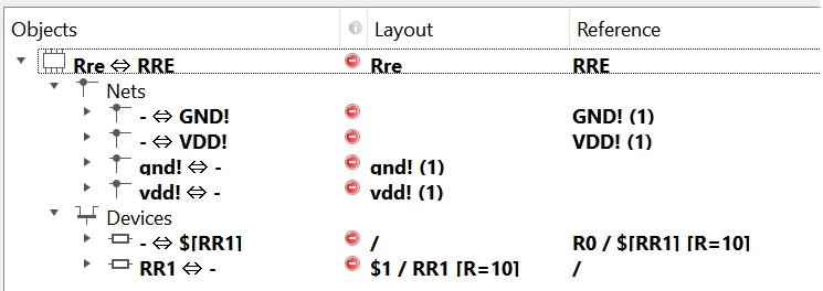
1. "mismatch" in Netlist Database Browse
Even if the device topology and parameters match, the result in the netlist browser is still mismatch.
I used the same custom comparator as @cgelinek_radlogic in "https://www.klayout.de/forum/discussion/comment/7750#Comment_7750".
Here is a comparison of the two netlists:
I have also tested it through the default comparator, the result turns out to be even stranger. Even if the extracted netlist does not change, the browser confirms that both vdd and gnd are connected to two nodes, and the topology does not match:
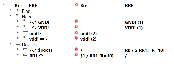

So how should I get the result of device match (by length and width instead of resistance value) in the browser?
2. more than the actual device in the variable device is puts
Too many device parameters were compared during the comparison, actually there is only one resistor in the gds file. This is no problem when there are only few devices in Layout, but if the number of devices to be verified is large, it will not be able to accurately determine the information of the mismatched device during the comparison process :
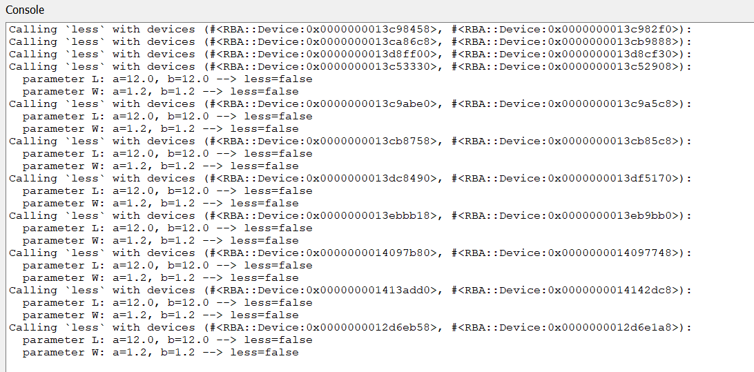
How should deal with this problem?
3. customized netlist generate
The default extracted netlist (by "target_netlist") only contains the resistance value, but the length and width of the resistance are more meaningful. Because if the length and width of the resistor are very small, the usual resistance value estimation methods have large tolerances.
How can I get the extractes netlist in the specified format?
Comments
Hier are the test file
@Bian
Thanks for the testcase and the nice description of the problem.
First of all there is a very simply explanation for the mismatch of the resistors: the models do not match.
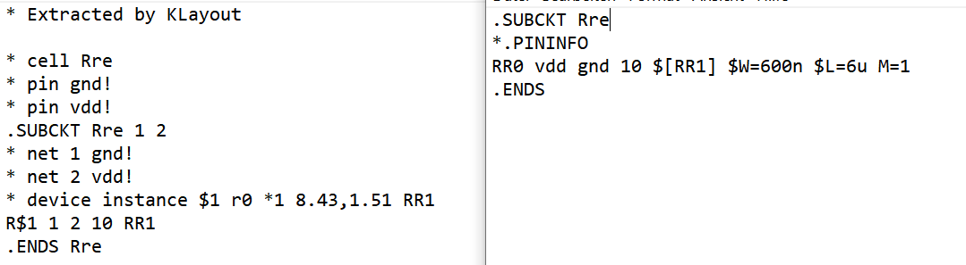
This line from the schematic:
will be read as model "$[RR1]" while the layout extracts model "RR1".
Is the "$[...]" notation some kind of standard and if so which? How do I read that?
Same is true for "$W" which for KLayout's Spice reader is not the parameter "W".
If I change the Spice line in the schematic to
I'll get a match. Still, the custom compare approach will fail, because as a matter of fact there is a bug too in KLayout (https://github.com/KLayout/klayout/issues/854) which means W and L is extracted 2 times too large by the default extractor. I'll fix that in the next release as well.
The "puts" method in the comparer is just for debugging - it's not intended to present the match result. As explained in the post you're referring to, the problem is that W and L are considered "hidden parameters" by the Resistor device class and are not taken into account for matching nor are displayed.
Hence, you do not see W and L in the browser, it's not netlisted and not compared. Right now, it's not possible to override the device class behaviour that disables W and L because KLayout's API does not provide the methods to customize device classes to this level. I'll see that I can fix that for the next release. Currently, only tedious workarounds exist (Comparer, netlist reader and writer delegates) and I'd rather not like to advertise these.
The code that has evolved in the discussions before is actually not correct. I'll show the corrected code here (see "FIXED:" comments for the changes I applied):
With this code, the resistor's length and width are extracted correctly and the comparer will compare W and L rather than R. Still, W and L are not shown in the browser nor netlisted. As mentioned, the leaner way is for me to enable customization of device classes. That'll be much easier. I have tried to briefly summarize the requirements here: https://github.com/KLayout/klayout/issues/855
I'll keep you updated.
Matthias
@Matthias
The original netlist is in pspice format from cadence, there are "$" before variable or modell name.
So I am also very interested in a another question, which format of netlist can klayout-netlist-reader read? Are there any dokumentation for it?
Thanks for your answer and help, and looking forward to next release!
@Bian Unfortunately there are too many Spice flavours. I recall even Cadence wasn't consistent within their own tools.
I took my knowledge from the ngspice user manual: http://ngspice.sourceforge.net/docs/ngspice-manual.pdf
Actually KLayout's netlist is an object and the API for building that netlist is exposed to Python or Ruby. This essentially enables building any kind of netlist reader in Python. So if one likes to implement CDL or HSPICE readers, please go ahead.
BTW: KLayout internally uses it's own format to represent netlists, geometry-annotated netlists and cross-reference information (l2n and lvsdb databases).
Matthias
@Bian
Hi! I use the pspice format from cadence too. So I am interested in the same question as you.
Could you please share how you deal with this problem if you have found the solution?
Thanks!
@WENSHIH
I now solve this problem by manual modifications, which mainly include removing the $ symbol before some parameters and adding a virtual resistance value to the resistor.
For example:
from
RR0 vdd! gnd! $[RR1] $W=600n $L=6u M=1to
RR0 vdd! gnd! 1 RR1 W=600n L=6u M=1If you need to do this often, you can write a python script to batch process it. The netlist I'm dealing with is relatively small, so I don't need to do that.
I can't think of all the differences at once
There are three main differences between the netlist format supported by KLayout and the CDL output:
"$" in ngspice means "value of" when applied to a variable.
Using the variable name bare, might result in the assignment
of the variable name rather than the variable value.
if Y=1 then
set X = Y ends up setting X to "Y" (if it doesn't fail altogether
for type)
set X = $Y ends up setting X to 1.
There is additional weirdness, like you can assign a text string
to a variable but then the variable will not print, but will echo.
So string variables need to be handled with more care and that
is probably what the "$" is about.
I imagine that there may be value in "keeping two sets of books"
(one extractor for LVS, a separate for actually getting a properly
and accurately functioning layout based SPICE simulation.
I have seen foundries maintain two sets of models for this,
when devices are emulated by subcircuit lashups of "feature
specific" elements (for example, a junction isolated NPN also
includes a lateral and a substrate PNP, which can't be fitted
by a single compact model if these devices have (or could
be driven into) activity. So there will be a "max accuracy
including abnormal operation" model tree, and one that has
only the "top-line" device (the NPN) that matches the schematic
and "lets sleeping dogs lie".
But the more pertinent question is how to arrange the extraction
details, for whichever is the case at hand (someday, both).
>
** ngspice-37 : Circuit level simulation program
** The U. C. Berkeley CAD Group
** Copyright 1985-1994, Regents of the University of California.
** Copyright 2001-2022, The ngspice team.
** Please get your ngspice manual from http://ngspice.sourceforge.net/docs.html
** Please file your bug-reports at http://ngspice.sourceforge.net/bugrep.html
** Creation Date: May 19 2022 12:54:22
ngspice 1 -> ngspice 1 -> set x=1
ngspice 2 -> print x
Error(checkvalid): vector x is not available or has zero length.
ngspice 3 -> print $x
1 = 1.000000e+00
ngspice 4 -> set y=x
ngspice 5 -> print y
Error(checkvalid): vector y is not available or has zero length.
ngspice 6 -> set y=$x
ngspice 7 -> print y
Error(checkvalid): vector y is not available or has zero length.
ngspice 8 -> print $y
1 = 1.000000e+00
ngspice 9 -> set z="this is z"
ngspice 10 -> print $x
1 = 1.000000e+00
ngspice 11 -> print $z
Error(checkvalid): vector this is not available or has zero length.
ngspice 12 -> print z
Error(checkvalid): vector z is not available or has zero length.
ngspice 13 -> echo z
z
ngspice 14 -> echo $z
this is z
ngspice 15 ->
<
@Bian

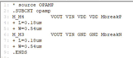
I have tried every netlist form in pspice, but I still couldn't have the same kind of form as yours.
Here is my schematic and the netlist of my schematic
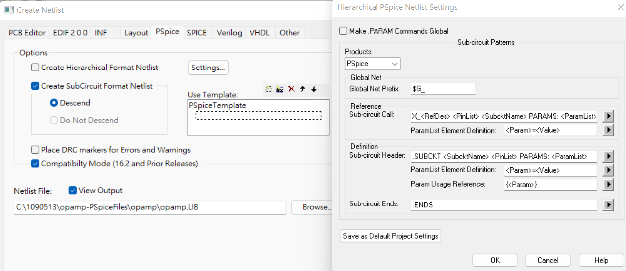
This is my format setting
Could you show me how you set the format or suggest me anything you thought I can improve
Thanks!
Here is my file. If it can let you more clearly about my problem, you can open it.
Using Perl, Python or in my case old timey shell / sed scripts
to massage netlists for various reasons, is a very done thing.
Whether it's optimizing parallel FETs / fingers into one single
device, or removing extraneous characters, or even building
veriloga elements from "chunks". Sometimes you don't need
the fanciest tool, but the simple one you cobble yourself.
Or buy your friendly neighborhood CAD lady a donut.
@WENSHIH
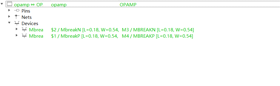
There are two errors in your File.
1, Regarding netlist, there is no "+" before the parameter
2, In lines 53 to 59 of the LVS-script, you are using the wrong model name (which does not match the netlist)
you should use "
MbreakP" and "MbreakN" instead of "PMOS" und "NMOS"After these two modifications you will get the correct result:
@WENSHIH
And our export format is different because we use different versions of the output software, but the resulting problem is the same, the output spice needs to be read by KLayout through certain modifications.
@WENSHIH
You can decide how you want to proceed depending on the frequency or number of your needs. If you need to process such pspice files often, it is better to have a script that can batch process them.
Most of the ones that are publicly available online don't work very well, because everyone has nuanced differences in their problems, even if they all use pspice, for example, the problem I have is
[]and$, but yours is the+before variable.If you don't encounter this problem often, you can just make a manual modification
@Bian
Thanks for your help! I have been stuck in this problem few days, after I followed your step, it has been successed.
I will try to write a script that can batch process them.
Thanks again!
It would be good if the LVS could tolerate dialect differences.
It might be expedient to do this by some "compatibility setting"
(ngspice has compatibility flags for some of the more popular
commercial simulators, as well as some guidance on netlist
massaging for compatibility).
The "+" is a very standard continuation character in most SPICEs
and its presence here seems unnecessary, probably a "style thing"
in the PSPICE netlisting templates (can you find, and alter, the
format to get a single line per device?). Like, one line for topology
and one for parameters (when it would all fit on one) seems to be
the plan, but perhaps you can find the handle at the source end
and save yourself some script writing.
Or maybe there is some facility in the simulator which will put
out a line-per-device listing (like, in ngspice, "listing" is the
command) and you could put that to a file, maybe cleaner than
the schematic based netlist.
@dick_freebird
Unfortunately, I have tried every format in pspice, but I still can't find the form that could get a single line per device,
Maybe I omitted something, but I didn't find out. I really hope that the LVS could tolerate dialect differences either.
Is it possible to make this kind of format in ngspice? If it can get a single line per device, I think it would be convenient!
We can develop the appropriate compatibility tools for dialect differences, or Mr Matthias open the interface to the netlist reader in klayout and override it. I think Mr Matthias does not always have time to handle so many requests.
"Mr Matthias" can handle this request, but I need to understand if it is possible to implement a reader that is able to differentiate between the formats or if it is required to specify the dialect used.
I tried to follow the SPICE notation I found in the ngspice documentation, although not in all details. The goal was to be able to parse a netlisted schematic, not to read a ready-for-simulation netlist (this will usually include testbenches or simulation models). I assume, other simulators use a slightly different syntax and maybe the reader can be made smart enough to digest multiple formats. However, if there are formats which are fundamentally incompatible, then there is need for another reader type and the user needs to specify the format he or she wants to read.
If you can describe the modifications you need in detail and ideally provide some test cases, you can file an ticket on GitHub (https://github.com/KLayout/klayout). It's fine with me to extend the SPICE reader to cover other dialects if possible.
Kind regards.
Matthias
It might be useful for the proponents of various simulator
netlist formats, to dig into their simulator's documentation
and see about options. There may be SPICE compatibility
settings that enforce more-standard formatting. If there are
no good options, then some exposition of the format that
-does- result would be fodder for developing "input filter"
scripting or internal parsing.
I have seen (as I mentioned) foundries that maintain two
sets of models for just this purpose. The ones for LVS
eliminate the parasitic elements from their subcircuit-
per-transistor models, so there are only the devices that
are indicated by the schematic symbols.
If you cared to, you could make a private copy of the
PSPICE model tree and modify the transistor models
to eliminate extended lines and extraneous (i.e. not-
checked) properties / params. Fix the problem at the source.
Probably two minutes per model card once you get the
motion down. Do the community a favor and write it up
when you find what works.
Now since ngspice purports to have PSPICE compatibility
(option) I wonder whether you could source PSPICE deck,
and do 'listing >layout_netlist.spice' and get something
that needs little or no massaging (being closer to standard
SPICE format once digested).
I have seen mostly "leading +" continuation (a dead-basic
SPICE syntax since SPICE2 at least) but also have seen
"trailing &" in one dialect (a corporate customized SPICE2G6).
I'm pretty sure there's a limited variation in this respect. But
other "netlisting breakers" will no doubt pop up and need
whacked.
@Matthias
Thanks for your help! Since I'm not familiar with extracting netlist from the pspice enough, I think I would take some time to summarize the modification I need. But I will try my best.
WENSHIH
I would bet that the netlisting "template" can be found, probably
as a property of the PSPICE symbol itself (but I am no PSPICE
expert). Try pushing down the hierarchy looking for pin and
property passing. The PSPICE output log may show you what's
being parsed along the way.
If you can find the library and its netlisting paraphernalia, then
you can copy and modify the netlisting format to match what
klayout can digest in your private copy. If that is the only change
then it's OK to use the original for simulation and the modified,
for connectivity verification.
All that said, maybe you would be better off with xschem as a
schematic capture / simulator interface tool. There, the symbol
netlisting is altogether visible and yours to control / modify. Of
course you'd have to recapture, but we're not talking that many
components. But maybe PSPICE is part of the frame, in which
you are told to sit.