Hello, when i start a layout ( saved as GDS files) , i give a name to each layer , but when i go back to layer specifications, the window show only the number of layer, but the name disappear . it disappear also on the up right area with layer stack list ,can you help please ?
@Nacer There are two kind of layer names: database layer names and the layer description you give each layer in the layer list.
GDS does not support database layer names, so you cannot use them in GDS.
If you talk about the layer description in the layer list, you need to save them in "layer properties files" with "File/Save Layer Properties". If you load a GDS file you can load the layer properties files with "File/Load Layer Properties".
Or you use a technology setup like @dick_freebird suggested.
I made my own layertables from paper sources, to
save as .lyp - this is essential in any case, if you mean
to keep working in a consistent environment. There you
can add the human readable names if you like.
I use the Technology just to make them easy to find and
auto-load the same setup from one session to the next.
Hi Nacer
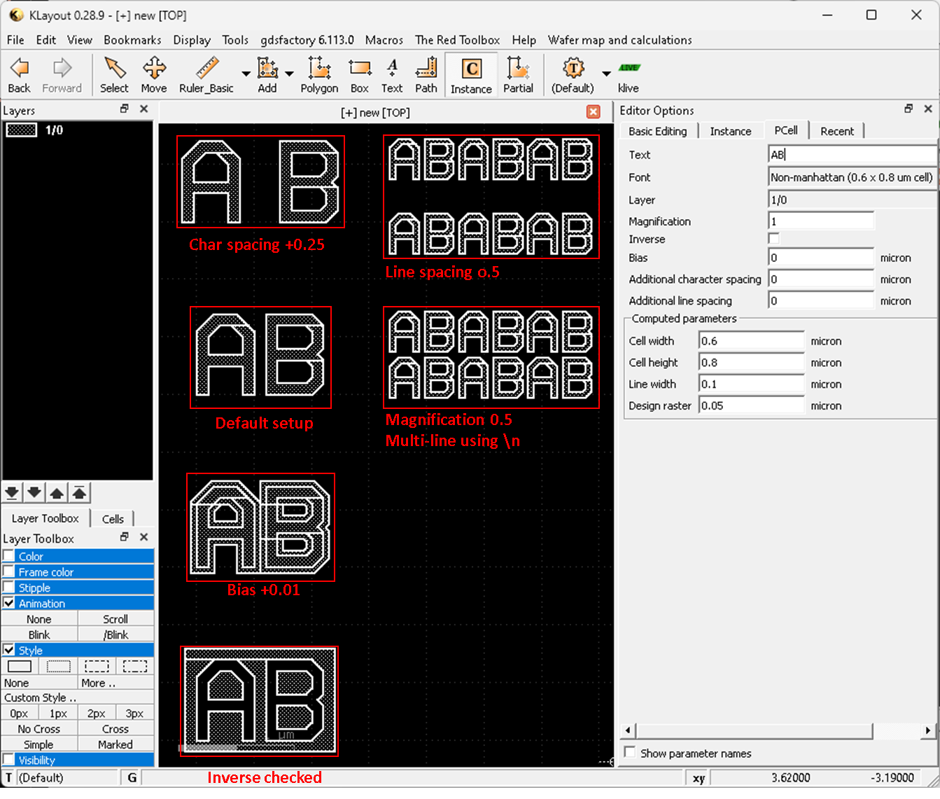
text can be added using pre-defined PCell in "basic" library
follow the step you can drop a instance of PCell in "Instance" panel
You can config a pcell text and size from "Pcell" tab while you drop-in the cell
or you can double click on the pcell to modify the parameters after you place the cell
following example showcase the effect of every parameter in the panel.
Many thanks for your prompt response . however , my wish is to add the text on a metal layer in order to be readable after the metal level manufacturing .
Regards
Nacer
@Nacer please take a look at @RawrRanger's nice description. This is the way to generate polygons ready for mask making. If you make them big enough and observe the design rules, you can read them on the final die.
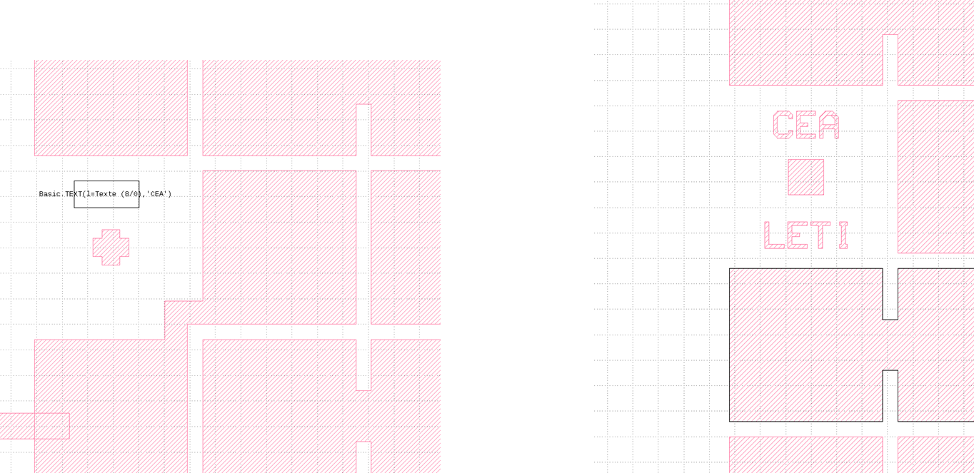
Hi Matthias, thanks for the reply . i folowed the @RawrRanger procedure , but , as you can see on the picture , i have a black rectangle ( left picture) but the text is not visible . my wish is to see the text as a whole part of a metal layer as it can be seen on the right , it's crazy but i cannot find how i have done this on a previous design .
Best regards
Nacer
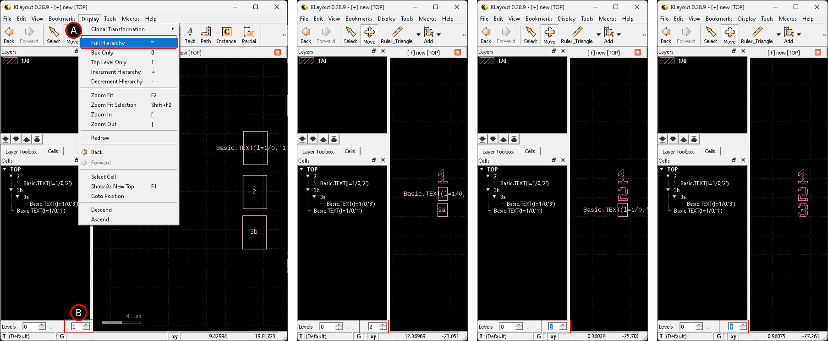
The text polygon existed in a pCell, and the pCell is placed inside your current cell.
which means to see this shape you need to increase the viewing hierarchy level to at least 2.
The way to adjust the level is as below, both (A) or (B) should work.
The following numer 1, 2, 3 shapes is placed in different cell hierarchy depth, by increasing the number you can filter to show shapes in certain hierarchy range.
There are two kinds of "text" available to you in klayout.
There is the basic GDS text object, created by the top-bar "Text", on layer current. This is what you'd use for things like basic layout labels ("Text/drawing layer,not to be printed), pin tagging (process layers, but not to be printed), feature recognition by Booleans with "get texted" and so on.
Then there is the "printable mask letters" text which is a scalable PCell based on some scripting. That comes from the top-bar "Instance ", through the PCell libraries. If you want human-visible mask art on your die, that's this one.
I've seen "side libraries" per process for the mask nums / letters, rather than PCells, in my career as the minimum printable has a lower limit set by process groundrules, nobody needs to waste space on bigger, and each developed process was a one-off (in my inside-foundry years). But for a tech-agnostic tool the PCells make sense (and you can make your own static LET_NUM library for your fave flow at any time as a result).
Hello dick_freebird , thanks for this complementary response . can you advice how i can perform a distance measurement between two centers of drawed circles ( i use the round corners function)?
thanks in advance
Best regards
Nacer
Re center-center measurement: graphically if these "circles" are
true circle PCells with a justified center I would just use Ruler and
watch for the origin mark to light up, to place the start and end.
If origin is true center then you could also just take the numbers
from property-edit window and do the calculator work outside.
But "rounded corners" may not be the same as actually executing
the "circle" PCell evaluation.

Comments
Somewhere in the Settings, there are options for what is
shown in the layer window.
You might also want to look at "Technologies" to make
the layers config you like, "stick".
@Nacer There are two kind of layer names: database layer names and the layer description you give each layer in the layer list.
GDS does not support database layer names, so you cannot use them in GDS.
If you talk about the layer description in the layer list, you need to save them in "layer properties files" with "File/Save Layer Properties". If you load a GDS file you can load the layer properties files with "File/Load Layer Properties".
Or you use a technology setup like @dick_freebird suggested.
Matthias
I made my own layertables from paper sources, to
save as .lyp - this is essential in any case, if you mean
to keep working in a consistent environment. There you
can add the human readable names if you like.
I use the Technology just to make them easy to find and
auto-load the same setup from one session to the next.
Thanks to all, clear now for me
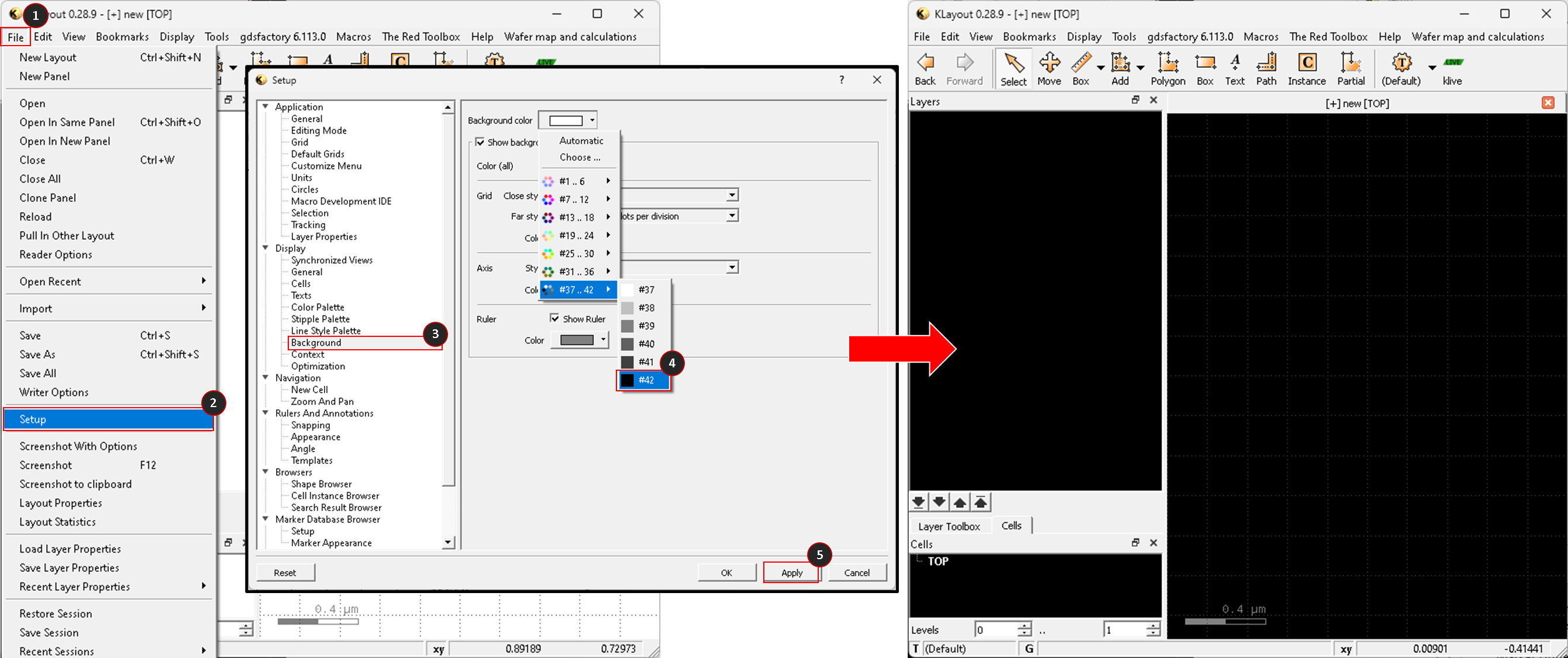
i want to change the font screen from white to black , can you help me please ?
Best regards
Nacer
Hi Nacer
You can follow this to change the background color
Many thanks .
Another question , how to create a text and put it on a design ?
Hi Nacer
text can be added using pre-defined PCell in "basic" library
follow the step you can drop a instance of PCell in "Instance" panel
You can config a pcell text and size from "Pcell" tab while you drop-in the cell
or you can double click on the pcell to modify the parameters after you place the cell
following example showcase the effect of every parameter in the panel.
Many thanks for your prompt response . however , my wish is to add the text on a metal layer in order to be readable after the metal level manufacturing .
Regards
Nacer
@Nacer please take a look at @RawrRanger's nice description. This is the way to generate polygons ready for mask making. If you make them big enough and observe the design rules, you can read them on the final die.
Matthias
Hi Matthias, thanks for the reply . i folowed the @RawrRanger procedure , but , as you can see on the picture , i have a black rectangle ( left picture) but the text is not visible . my wish is to see the text as a whole part of a metal layer as it can be seen on the right , it's crazy but i cannot find how i have done this on a previous design .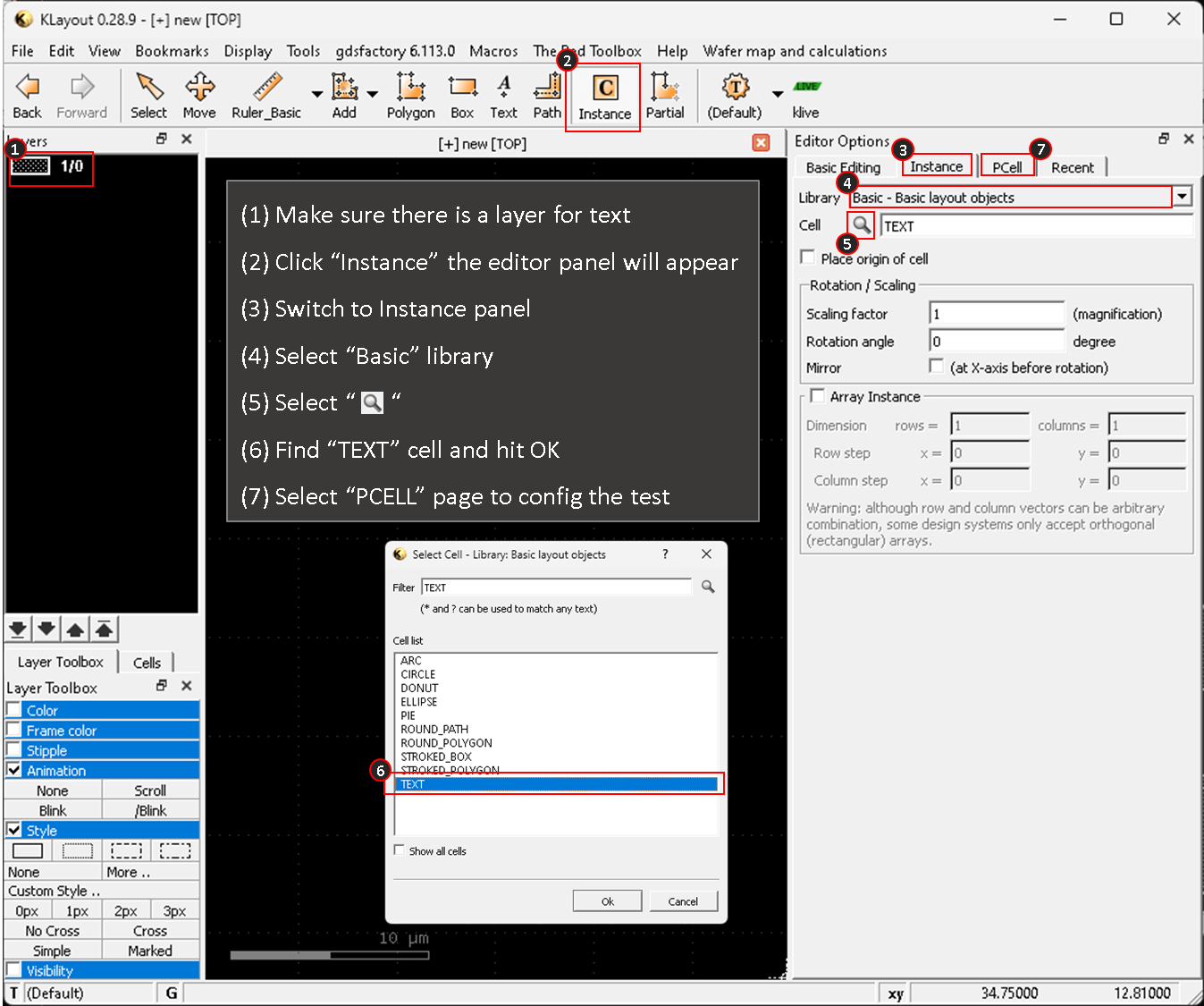
Best regards
Nacer
Wrong picture
Hi Nacer,
The text polygon existed in a pCell, and the pCell is placed inside your current cell.
which means to see this shape you need to increase the viewing hierarchy level to at least 2.
The way to adjust the level is as below, both (A) or (B) should work.
The following numer 1, 2, 3 shapes is placed in different cell hierarchy depth, by increasing the number you can filter to show shapes in certain hierarchy range.
Thanks RawsRanger for your reactivity
@RawrRanger Thanks, great explanation!")
Matthias
There are two kinds of "text" available to you in klayout.
There is the basic GDS text object, created by the top-bar "Text", on layer current. This is what you'd use for things like basic layout labels ("Text/drawing layer,not to be printed), pin tagging (process layers, but not to be printed), feature recognition by Booleans with "get texted" and so on.
Then there is the "printable mask letters" text which is a scalable PCell based on some scripting. That comes from the top-bar "Instance ", through the PCell libraries. If you want human-visible mask art on your die, that's this one.
I've seen "side libraries" per process for the mask nums / letters, rather than PCells, in my career as the minimum printable has a lower limit set by process groundrules, nobody needs to waste space on bigger, and each developed process was a one-off (in my inside-foundry years). But for a tech-agnostic tool the PCells make sense (and you can make your own static LET_NUM library for your fave flow at any time as a result).
Hello dick_freebird , thanks for this complementary response . can you advice how i can perform a distance measurement between two centers of drawed circles ( i use the round corners function)?
thanks in advance
Best regards
Nacer
Re center-center measurement: graphically if these "circles" are
true circle PCells with a justified center I would just use Ruler and
watch for the origin mark to light up, to place the start and end.
If origin is true center then you could also just take the numbers
from property-edit window and do the calculator work outside.
But "rounded corners" may not be the same as actually executing
the "circle" PCell evaluation.
Hi Nacer,
a similar disscussion about center measurement, for your reference.
https://www.klayout.de/forum/discussion/894/slice-a-shape-into-two-parts#latest
Or, simply install the center ruler plugin from the package.